DGP2641-EI14.fm Page -3 Monday, February 20, 2006 9:35 AM LCD Keypad V2.
DGP2641-EI14.
DGP2641-EI14.fm Page -1 Monday, February 20, 2006 9:35 AM Table of Contents Introduction..................................................... 1 Specifications ...................................................... 1 Installation....................................................... 2 Connecting Keypad Zones .................................. 2 Programmable Output ......................................... 3 Programming .................................................. 4 Entering Module Programming Mode.
DGP2641-EI14.fm Page 0 Monday, February 20, 2006 9:35 AM Confidential Mode Timer ................................... Time Display Option .......................................... Muting................................................................ Beep on Exit Delay ............................................ Chime on Zone Closure..................................... Beep on Trouble ................................................ Keypad Tamper Enable.....................................
DGP2641-EI14.fm Page 1 Monday, February 20, 2006 9:35 AM 1.0 Introduction Thank you for choosing Paradox Security Systems. Digiplex security systems offer advanced technology and provide reliable security protection and powerful features that are easy to use. The elegant and user-friendly LCD Keypad allows easy access to the security system's functions and information at the touch of a button. Since all programming is accomplished through the keypad, please read this manual carefully. 1.
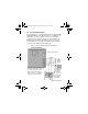
DGP2641-EI14.fm Page 2 Monday, February 20, 2006 9:35 AM 2.0 Installation The LCD keypad (DGP2-641BL) is connected to the control panel's combus in a star and/or daisy chain configuration. The 4wire combus provides power and two-way communication between the control panel and all modules connected to it. Connect the four terminals labeled red, black, green and yellow of each keypad to the corresponding terminals on the control panel (refer to Figure 2.1 on page 3).
DGP2641-EI14.fm Page 3 Monday, February 20, 2006 9:35 AM 2.2 Programmable Output Each keypad has one on-board PGM. A PGM is a programmable output that switches to its opposite state (i.e. a normally open PGM will close) when a specific event has occurred in the system (refer to section 5.0 on page 14). Upon activation, the PGM can provide 50mA to any device connected to it. If the current drawn is to exceed the current limit, a relay should be connected to the PGM as shown in Figure 2.1. Figure 2.
DGP2641-EI14.fm Page 4 Monday, February 20, 2006 9:35 AM 3.0 Programming To program the DGP2-641BL keypad, enter Module Programming Mode and then enter the desired section followed by the required data. When programming the keypad, use the keypad’s programming sheets (found in the Digiplex Modules’ Programming Guide) to keep track of which sections were programmed and how. We strongly recommend you read this entire manual before you begin programming.
DGP2641-EI14.fm Page 5 Monday, February 20, 2006 9:35 AM serial number is located on the keypad's PC board or enter section [000] in Step 3 to view the keypad’s serial number. 3.2 Programming Methods The following methods can be used when programming the keypad: 3.2.1 Feature Select Programming Some sections are programmed by enabling or disabling options. Within the sections, numbers from [1] to [8] represent a specific keypad option.
DGP2641-EI14.fm Page 6 Monday, February 20, 2006 9:35 AM source’s data. If you want to program more than one keypad with the source’s data, enter the serial numbers of the keypads one at a time. 6. Once you have entered the serial numbers of the keypads you want to program, press the [ACC] key. 3.4 Memory Key Sections [510] and [520] Download information to and from an LCD keypad using the memory key (PMC-3).
DGP2641-EI14.fm Page 7 Monday, February 20, 2006 9:35 AM 3.6 Copy the Keypad Contents to the Memory Key Section [520] 1. Insert the memory key onto the keypad’s connector labelled “KEY” (refer to Figure 2.1 on page 3). Ensure that the write protect jumper is ON (refer to Figure 3.1). 2. To copy the contents to the memory key, enter the keypad’s programming mode and enter section [520]. 3. After the confirmation beep, wait 5 seconds and remove the memory key after the second confirmation beep.
DGP2641-EI14.fm Page 8 Monday, February 20, 2006 9:35 AM 4.0 System Options 4.1 Partition Assignment Section [001]: Options [1] to [8] Each keypad in the system can be assigned to one or more partitions. In section [001], options [1] to [8] represent partitions 1 through 8 respectively. To assign the keypad to a partition, simply enable the option that corresponds to the desired partition. By default, partitions 1 to 8 are enabled.
DGP2641-EI14.fm Page 9 Monday, February 20, 2006 9:35 AM 4.4 Display Entry Delay Timer Section [003]: Option [3] Based on the user's needs, an Entry Delay Timer will be programmed to provide the user time to enter their user access code before the alarm is triggered. The Entry Delay Timer's countdown can be displayed on the LCD screen. Option [3] OFF= Will not display the Entry Delay Timer (default) Option [3] ON= LCD screen will display Entry Delay Timer 4.
DGP2641-EI14.fm Page 10 Monday, February 20, 2006 9:35 AM Option [4] OFF = Normal Mode (default) Option [4] ON = Confidential Mode Option [5] OFF = LCD screen activated by entering an access code (default) Option [5] ON = LCD screen activated by pressing a button Figure 4.1: LCD Screen 4.6 Confidential Mode Timer Section [007] Section [007] determines the amount of time without action before the keypad enters Confidential Mode.
DGP2641-EI14.fm Page 11 Monday, February 20, 2006 9:35 AM 4.8 Muting Section [004]: Option [1] The keypad can be programmed not to emit audible sounds, including Chimed zones. During Muting, the keypad will only emit the Confirmation Beep, Rejection Beep, and beep when a button is pressed. Option [1] OFF = Audible sounds (default) Option [1] ON = Mute 4.9 Beep on Exit Delay Section [004]: Option [2] The keypad can beep once every second during the Exit Delay Timer.
DGP2641-EI14.fm Page 12 Monday, February 20, 2006 9:35 AM 4.11 Beep on Trouble Section [005]: Options [1] to [4] Potential troubles have been sorted into groups. With these options enabled, the keypad will emit an intermittent beep tone whenever a trouble condition from the Trouble Groups occurs in the system. The intermittent beep will remain activated until the user enters the Trouble Display or if the trouble is resolved.
DGP2641-EI14.fm Page 13 Monday, February 20, 2006 9:35 AM Option [5] OFF = Keypad's tamper is disabled (default) Option [5] ON = Keypad's tamper is enabled 4.13 Combus Voltmeter The combus Voltmeter provides a real-time display of the voltage so you can verify if the bus is supplying sufficient power at the keypad’s location. The readings will appear on the LCD screen. A reading of 10.5V indicates that the voltage is too low.
DGP2641-EI14.fm Page 14 Monday, February 20, 2006 9:35 AM 5.0 Programmable Output Options 5.1 PGM State Section [006]: Option [1] The keypad's on-board PGM can be set as normally open or normally closed. When an open PGM is activated, it will close the circuit from ground and enable any devices connected to it. When a closed PGM is activated, it will open the circuit and disable any devices connected to it. When the PGM Activation Event occurs (see section 5.
DGP2641-EI14.fm Page 15 Monday, February 20, 2006 9:35 AM 5.3 PGM Base Time Section [006]: Option [3] If the keypad's on-board PGM is set in PGM Timed Mode (see section 5.2 on page 14) you must define whether the value programmed in section [008] is in minutes or seconds. Option [3] OFF = PGM Base Time is 1 second (default) Option [3] ON = PGM Base Time is 1 minute 5.
DGP2641-EI14.fm Page 16 Monday, February 20, 2006 9:35 AM 5.6 PGM Activation Event Sections [009] to [012] The PGM Activation Event determines which event will activate the keypad's on-board PGM output. The Event Group specifies the event, the Feature Group identifies the source, and the Start # and End # sets the range within the Feature Group. Use the PGM Programming Table in the Digiplex Modules’ Programming Guide to program the keypad’s PGM Activation Event.
DGP2641-EI14.fm Page 17 Monday, February 20, 2006 9:35 AM 6.0 Message Programming Sections [101] to [148], [200] to [204], and [301] to [396] Each section contains one message with a maximum of 16 characters. For more details and to record any changes, use the Digiplex Modules’ Programming Guide. The DGP-NE96 control panel has up to 8 partitions, 96 zones and up to 999 user codes. The LCD keypad only allows you to program the messages for up to 4 partitions, 48 zones and 96 user codes.
DGP2641-EI14.fm Page 18 Monday, February 20, 2006 9:35 AM Table 6.1: Message Programming Keys Key Press Key Once Press Key Twice Press Key Three Times [1] [2] [3] [4] [5] [6] [7] [8] [9] A D G J M P S V Y B E H K N Q T W Z C F I L O R U X 6.1 Special Function Keys [STAY] - Insert Space Pressing the [STAY] key inserts a blank space in the current cursor position. [FORCE] - Delete Pressing the [FORCE] key will delete the character or blank space found at the current cursor position.
DGP2641-EI14.fm Page 19 Monday, February 20, 2006 9:35 AM [BYP] - Lower Case / Upper Case Every time the [BYP] key is pressed it will toggle the case setting from lower to upper case and vice versa. [MEM] - Special Characters After pressing the [MEM] key, the cursor will turn into a flashing black square. Using Table 6.2 on page 20, enter the 3-digit number that represents the desired symbol.
DGP2641-EI14.fm Page 20 Monday, February 20, 2006 9:35 AM Table 6.
DGP2641-EI14.fm Page 21 Monday, February 20, 2006 9:35 AM Warranty Paradox Security Systems Ltd. (“Seller”) warrants its products to be free from defects in materials and workmanship under normal use for a period of one year. Except as specifically stated herein, all express or implied warranties whatsoever, statutory or otherwise, including without limitation, any implied warranty of merchantability and fitness for a particular purpose, are expressly excluded.
DGP2641-EI14.
DGP2641-EI14.
DGP2641-EI14.fm Page 24 Monday, February 20, 2006 9:35 AM For technical support in Canada or the U.S., call 1-800-791-1919 for English or 1-866-912-0600 for French, Monday to Friday from 8:00 a.m. to 8:00 p.m. EST. For technical support outside Canada and the U.S., call 00-1-450-491-7444, Monday to Friday from 8:00 a.m. to 8:00 p.m. EST. Please feel free to visit our website at www.paradox.ca. 780 Industriel Blvd., Saint-Eustache (Quebec) J7R 5V3 CANADA Tel.: (450) 491-7444 Fax: (450) 491-2313 www.