ePowerSwitch (iSWITCH) User’s Manual 20020925 Rev4
Table of Contents Warnings 3 Quick Install Procedure 4 Introduction 7 Remote Power Manager (iSwitch) Features 7 iSwitch Package 7 Setup Procedure 8 1. Setup via the USB Port 8 2. Setup via the Serial Port 18 3. Setup via the Ethernet Port 25 Telnet Configuration 26 Web-Based Configuration 31 Firmware Upgrade Procedures 39 Telephone Access Interface 44 Daisy Chaining 45 Troubleshooting 46 Appendix 47 1. Communities 47 2. Gateways 47 3. IP Address 47 4.
NOTICE: This equipment has been tested and found to comply with the limits for a “Class B digital device, pursuant to Part 15 of the FCC rules. These limits are designed to provide reasonable protection against harmful interference when the equipment is operated in a commercial environment. This equipment generates, uses and can radiate radio frequency energy and if not installed and used in accordance with the instruction manual, may cause interference to radio communications.
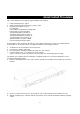
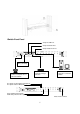
Quick Install Procedure This section will guide you through the quick installation of the iSwitch. 1. 2. 3. Install mounting brackets: page 4. Install all input and output connections: pages 5 and 6. Program you IP address: page 9. For USB setup: a) Insert Driver Setup Diskette in floppy drive. b) Run Setup.exe from floppy drive. c) Program IP address per Page 15. d) Program Subnet mask per Page 15. e) Program Default Route per Page 15. f) Program DNS Server per Page 15.
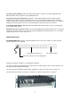
iSwitch-Front Panel Setup via USB Port Setup via RS232 Port Setup via Ethernet Port iLink Port is for Daisy Chaining Ring On/Reset Port – Connect a telephone line to control the iSwitch External Modem is required for Pager Function Connect to the network to control the iSwitch Receptacle Control Status LED (Green) Receptacle Status LED (Red) Active Module LED (Yellow) Momentary switch for Receptacle Master Power Switch 5
Receptacle Status LED (Red): When the LED is illuminated the receptacle is on and providing AC Power. When the LED is off the receptacle is not providing AC Power. Receptacle Control Status LED (Green): When the control LED is illuminated, the momentary switch is disabled and the output receptacle is programmed for remote control. When the LED is off, the momentary switch is active and the receptacle may be turned on or off by pressing and releasing the switch.
Introduction The Remote Power Manager (iSwitch) is a network-manageable, intelligent power control unit designed to provide control of power for up to eight electrical devices. NOTE: If the iSwitch is turned off by the master power switch, you have to wait approximately thirty seconds before restarting the iSwitch to allow the iSwitch to internally reset. iSwitch Features Internet ready — Individually control each of the eight AC receptacles by using a Web Browser.
Setup Procedure This section describes the setup procedures of the iSwitch when you connect it to the network. NOTE: The minimum requirement to operate the iSwitch is to set the IP address. There are four different ways to setup the iSwitch. 1. Setup the IP Address via the USB port (software included). Requires Windows 98 or higher. 2. Setup the IP Address via the Serial port using Hyper Terminal. Requires Hyper Terminal version 3.0 or higher. 3.
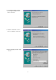
8.The Hardware wizard will guide you through installing the USB Driver. Click Next. 9. Hardware wizard will search for the best USB Driver. Click Next. 10. Check, Specify a location. Click Browse.
11. Open the appropriate 3½″ Floppy Drive. Open the USB folder. Open the Driver folder. Click OK. 12. Windows will search for the new USB Driver. Click Next. 13. Windows has found the USB Driver for the USB device. Click Next.
14. Windows has found the best Driver for this USB device. Click Next. 15. Windows is copying the USB Driver files to your “C:” drive. Click Next 16.Windows is finished installing the USB Driver. Click Finish. To your “C:” drive.
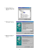
17. On the Desktop, right click “My Computer”. Open Properties. 18. Open the Device Manager. Wait for approximately 30 seconds for the “Human Interface Device” to appear. Open the Human Interface Device. Click on “Usbinterface power device”. Click OK. 19. Open Windows Explorer. Open the appropriate 3½″ Floppy Drive. Open the USB folder. Open USBSetup.exe. Note: The USB setup icon must be green before you can run the USB setup program. 20.
21. This is the Power Device Configuration Tool screen. On the Toolbar open Configuration. Then open System. 22. This is the System Parameter Configuration screen fill in all the information: the IP Address, the Subnet Mask, the Default Route (Gateway) and the DNS Server. Use the Tab key to move from one field to the next field. Then click OK.
23. This is the Power Device Configuration Tool screen. After you have entered in all of the pertinent information, you have to Update and Restart to save all the information that was entered into the System Parameter Configuration screen. The Update and Restart icon (with the red arrow) is right beneath the “Device” drop down menu. 24. Enter the Supervisor Name and the Supervisor Password. The Default Supervisor N ame and the Supervisor Password is admin (lower case).
25. This is the Power Device Configuration screen. Click Yes to Update the Power Device. 26. This is the Device Parameter Transmitting screen. The Power Device is being Updated.
27. The Power Device has been successfully updated. Click OK. 28. The Power Device has to be Restarted. Click Yes. 29. The USB Setup Procedure is complete. The iSwitch is fully operational.
iSwitch and from the computer. Plug the Ethernet Cable into the iSwitch and after about thirty seconds the Link LED will start blinking, now you can communicate with the iSwitch. The Ping command is supported at this time. Startup a Browser and type in the IP Address. The default password is admin (lower case). Go to the section in the User’s Manual titled “Web-Based Configuration” it will guide you through the Web pages. Setup via the Serial Port NOTE: When using Hyper Terminal use Version 3.0 or higher.
7. Connect using the appropriate Com port. Click OK 8. Configure the port settings. Bits per second: “115200”, Data bits: “8”, Parity: “None”, Stop bits: “1”, Flow control: “None”. Click OK 9. On the Toolbar open the File menu, and then open Properties.
10. Open the Settings Tab. Function, arrow and ctrl keys act as: Terminal Keys, Backspace key sends: Crtl+H, Emulation: VT100, Telnet terminal: VT100, Backscroll buffer lines: 500. Click OK. 11. Plug the iSwitch’s power cord into the AC outlet and turn the iSwitch on. 12. When the message “Press ‘/’ key within 5 seconds to enter console configuration” appears press the forward slash key (/) within the 5 seconds or the iSwitch will time out and then you have to start over. 13.
14. Ctrl-Z moves the cursor down and Ctrl-W moves the cursor up. Pick Network, then hit enter. 15. Enter in the IP Address, the Gateway Address, the Subnet Mask and the DNS (all required). Hit the “Escape” key to return to the main menu.
16. Arrow down to PPP Config and hit enter. Enter in the ISP dial number, the ISP account/password and the enable/disable dial-out interface (not required). Hit the “Escape” key to return to the main menu. 17. Arrow down to Mail and hit enter. Enter in the SMTP Server (not required). The user can add or delete email addresses. Hit the “Escape” key to return to the main menu.
18. Arrow down to Trap and hit enter. This screen allows the user to send Traps about the UPS to ten IP Addresses (not required). Also, you may determine the severity levels and what type of access, read only or read and write, to assign to a particular IP manager. Hit the “Escape” key to return to the main menu. 19. Once you have finished with the entire configuration, cursor down to Save_Restart and hit enter. Make sure you want to overwrite the old settings (y/n)? Hit the y key, then hit enter.
20. After rebooting the system, the new settings will be activated. Reboot (y/n)? Hit the y key then hit enter. Once the system has rebooted, cursor down to Exit then hit enter. 21. The Serial Setup Procedure is complete. The iSwitch is fully operational. Unplug the DB9 female-to-female Serial Cable from the iSwitch and from the computer. Plug the Ethernet Cable into the iSwitch and after about thirty seconds the Link LED will start blinking, now you can communicate with the iSwitch.
6. This is an example. At the MS-DOS Prompt type: arp –s 192.166.7.19 52-54-4c-19-ad-90. Then hit enter. The first string is the IP Address; the second string is the MAC Address (which can be found on the front of the iSwitch). 7. At the MS-DOS prompt type: route add 192.166.7.19 210.67.4.155. Then hit enter. The first string is the IP Address and the second string is the Gateway Address. NOTE: The PING Command is not supported at this time. 8. At the MS-DOS Prompt type exit. Then hit enter. 9.
Telnet Configuration This section will guide you through finishing the configuration of the iSwitch using Telnet. NOTE: You must complete the appropriate Setup Procedure before proceeding with the Telnet Configuration. NOTE: You must have given the iSwitch an IP Address. NOTE: The connection by telnet client limits only 2 users. NOTE: Telnet client connects to CIC card will be timeout over 75 sec. The Ethernet cable is connected to the iSwitch and the iSwitch is on. 1.
4. Pick Network, then hit enter. 5. Pick IP, then hit enter. Input your IP Address, Gateway Address, Subnet Mask and the DNS (all required). Then hit the left arrow key to exit to the main menu.
6. Arrow down to PPP Config and hit enter. Enter in the ISP dial number, the ISP account/password and the enable/disable dial-out interface (not required). Hit the left arrow key to return to the main menu. 7. Arrow down to Mail and hit enter. Enter in the SMTP Server (not required). The user can add or delete email addresses. Hit the left arrow key to return to the main menu. 8. Arrow down to Trap and hit enter.
read and write, to assign to a particular IP manager. Hit the left arrow key to return to the main menu. 9. Once you have finished with the entire configuration, arrow down to Save_Restart and hit enter. Make sure you want to overwrite the old settings (y/n)? Hit the y key, then hit enter.
10. After rebooting the system, the new settings will be activated. Reboot (y/n)? Hit the y key then hit enter. 11. The iSwitch has rebooted to activate the new settings. Click OK. Arrow down to exit then hit enter. 12. At the MS-DOS Prompt type exit, then hit enter. 13. The Telnet Configuration is complete. The iSwitch is fully operational. After about thirty seconds the Link LED will start blinking, now you can communicate with the iSwitch. The Ping command is supported at this time.
Web-Based Configuration This section will guide you through the Web-Based-Configuration and the Web Pages of the Remote Power Manager (iSwitch). NOTE: You must complete the appropriate Setup Procedures before proceeding with the Web-BasedConfiguration. The Ethernet cable is connected to the iSwitch and the iSwitch is on. 1. 2. 3. Startup a Web browser. Type in your IP Address. Next you will be asked for the User Name and Password. The default Name and Password is admin. Enter the password, then hit enter.
4. This is the screen where you can set the Network parameters. After you have finished filling in all of the information, click Save.
5. The PPP connection is useful if it is not possible to make a direct network connection to the iSwitch. An external modem is needed to connect to the front serial port of the iSwitch. The iSwitch support two ways using modem to connect directly. ISP After dialing in the remote user must hang up after the third ring.
6. This is the screen where you set the Date and Time. After you have finished filling in the information, click Save. 7. This is the screen where you can change the Administrator’s Name and Password. After you have finished filling in the information, click Save. NOTE: The Supervisor’s name and password can be from 1 to 19 digits. The Supervisor’s name and password is not limited to an alphanumeric character (i.e. a#1b$2z%9).
8. This is the screen where the administrator can enable the application program interface to certain users. After you have finished filling in the information, click Save. (Optional) 9. This is the screen where the administrator can give certain rights to certain users. After you have finished filling in the information, click Save. 10. This is the screen where you can upgrade to the latest version of software. After you have finished filling in the information, click YES.
11. After filling in all of the information be sure to Save and Restart before exiting the program. iSwitch 12. This screen allows the user to see the status of the iSwitch. The user can control each receptacle individually or all of them at the same time. The iSwitch has to be setup in the remote mode to control the receptacles via the Internet. The iSwitch can also be setup for the local mode. The user can control the receptacles by the momentary switches on the front panel.
13. a. ID Address Configuration and Identification: Since 16 iSWITCHs can be daisy chained together to share one CIC, each unit can be individually named. b. Name: The name of each outlet can be labeled to whatever you like it to be called (i.e. server1, DSL modem or webserver1). c. Power Resume Delay: The power resume delay is convenient for sequential startup. d. Ring On/Reset: Each outlet can be individually programmed to enable ring On/Off or reset. And phone control. (Optional, see P.
14.This screen allows the User to schedule daily/weekly shutdowns and restarts of individual receptacles (be sure to check the appropriate box). The safe shutdown is dedicated to Microsoft Windows NT (4.0, 2000, workstation and server). Click on the corresponding outlet to enable the safe shutdown feature. The safe shutdown feature has a configurable delay time to safely shutdown the NT server. Then click Save. 15.This screen allows the User to depend on the iSwitch event to set notification.
a. Pager Input the code defined by user himself to Alarm-Add and Alarm-Remove. b. Broadcast It must run an application in the client to receive this broadcast message. c. Logging Enable the event logging function.
d. Trap Set the SNMP trap. e. Mail Send the event to the user pre-set email account.
16. This screen allows the user to check the iSwitch event log. The Web-Based Configuration is complete. The iSwitch is fully operational. Firmware Upgrade Procedures Firmware Upgrade via TFTP With a Web browser, click on “Software upgrade”, input TFTP server’s IP address and go. Make sure that the firmware file (For example: ups.bin) is located in the default directory of the TFTP server. Firmware Upgrade via Serial Port: NOTE: When using Hyper Terminal use Version 3.0 or higher.
3. Once the message “Check udram” appears hit the “c” key. Then at the cursor type “upall” then hit enter. Once the User hits enter, you have approximately thirty seconds to complete the next four steps. 4. Go to the tool bar and select Transfer. Open Send File.
5.Select “X modem” under Protocol. 6. Click Browse. Look in the location where the Firmware upgrade software is located. Select the File name: “test.bin” and click open.
7. Click Send. 8. The Firmware upgrade will take approximately eight minutes to complete.
9. The Firmware upgrade is complete. NOTE: The user has to reconfigure all of the settings after the Firmware upgrade is complete, because all of the user’s settings will default to the original default settings.
Telephone Access Interface 1. Dial up the iSwitch. 2. After three rings the iSwitch will respond by sending out three short beeps to the caller. Then the iSwitch waits for the user to enter the password. 3. The user enters an access password (default password is 123456789#). 4. The iSwitch will send out three short beeps to confirm a successful login, or one long beep to deny access. 5. Once logged in, the remote user can punch in 4-8 digits.
Daisy Chaining The Remote Power Manager (iSwitch) can be Daisy Chained up to a maximum of sixteen units. Each iSwitch in the Daisy Chain must have its own unique identification number. The default ID# is “0 “. The first iSwitch must have the Internet Power Management Card install and must be configured before you can begin Daisy Chaining any additional RPMs. Only the first iSwitch requires the Internet Power Management Card.
16. 17. 18. 19. Plug the third iSwitch's power cord into utility power. Turn the master power switch on. Configure the third iSwitch's ID number (each iSwitch must have it's own unique ID#, the default ID# is "0"). If there are only three RPMs required for this application, then this completes the Daisy Chaining procedure and the RPMs are ready for use. 20. If your application requires additional RPMs (maximum of sixteen), then repeat steps 13-19 of the Daisy Chaining procedure.
Troubleshooting Problem: Solution: The TES (Terminal Emulation Software) does not display anything. Make sure the TES’s communication parameters are correct. They should be 115200-baud rate, no parity, 8-data bits, and 1 stop bit. The cable is a DB9 Female-to-Female serial cable. Problem: Solution: Solution: Solution: Solution: Solution: Solution: Problem: Solution: Solution: The NMS cannot ping the Remote Power Manager (iSwitch).
Appendix This section discusses: Communities, Gateways, IP Addresses, and Sub net masking. Communities A community is a string of printable ASCII characters that identifies a user group with the same access privileges. For example, a common community name is “public.” For security purposes, the SNMP agent validates requests before responding. The agent can be configured so that only trap managers that are members of a community can send requests and receive responses from a particular community.
Subnetting and Subnet Masks Subnetting divides a network address into sub-network addresses to accommodate more than one physical network on a logical network. For example: A Class B company has 100 LANs (Local Area Networks) with 100 to 200 nodes on each LAN. To classify the nodes by its LANs on one main network, this company segments the network address into 100 subnetwork addresses. If the Class B network address is 150.1.x.x, the address can be segmented further from 150.1.1.x through 150.1.100.x.
Glossary The Glossary section defines the terms used in the Computer Interface Card (CIC) -MP environment. Agent Dry Closure Input Dry Closure Output Ethernet Gateway IP IP Address MAC MIB NC NIC NMS NO OID Personality Router RS-232 SNMP Sub-Agent TCP/IP Implemented SNMP applications in network elements (hosts). Agents perform the network management’s functions as requested by the network administrator from an NMS. Non-powered contact type inputs—switch, relay contact, open-collector.
TES TFTP Server UDP/IP UPS Terminal Emulation Software—Communications program to transform a personal computer into a terminal for the purpose of data communications. Trivial File Transfer Protocol Server—A host to provide services according to TFTP; a TCP/IP standard protocol for file transfer with minimal capability and overhead depending on UDP for its datagram delivery service. User Datagram Protocol/Internet Protocol—A TCP/IP standard protocol.