
User's Manual


5
Pre-installation Considerations
Establish a site installation plan based upon desired central coverage area
• The inside and outside antenna must have a separation distance of 20 feet or
greater, the outside antenna must be outside and separated from the inside antenna
by an exterior wall, and both antennas must be in a vertical position.
• Identify the outside antenna location. If the outdoor coverage area is very poor,
the outside antenna should be placed on the side of the building where the signal
is the strongest. If the signal is equally strong outdoors, the outside antenna
should be placed in a secure, unobstructed area. On an RV the antenna can be
attached to the back ladder or on the side of the RV. On a boat the outside antenna
should be mounted clear of metal objects, 3’ from other antennas and as high as
possible.
• For maximum coverage the location of the indoor antenna should have a direct
line-of-site to as much of the coverage area as possible. The indoor antenna must
be used with 18” cable and antenna stand. Never use the inside antenna directly
connected to DA4000SBR amplifier/repeater unit.
• Based upon the desired coverage area, choose a central location for the
DA4000SBR unit. The location of the DA4000SBR unit must be accessible
within reach of the supplied 30’ cable (PowerMax
TM
50’ and 75’ cables sold
separately) and within 6’ of a power receptacle (or an extension cord can be
used). The DA4000SBR unit is not waterproof and must be kept in a dry location.
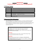
c. ELECTRICAL POWER
To maximize installation flexibility, the DA4000SBR system includes 2 power cord
options.
WARNING!
Only the provided power cables are to be used with the DA4000SBR
system. Using any other power cables will harm the DA4000SBR
amplifier/repeater unit, can be detected and voids the warranty.
To plug into a standard 110 VAC receptacle use P/N DP255, a 110 VAC to 5VDC Power
Supply. For use on a boat or RV, plug P/N DP515, a 12 VDC to 5 VDC Power Cable,
into a 12 VDC cigarette style power receptacle.
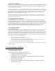
d. AMPLIFIER/REPEATER STATUS
The DA4000SBR unit is designed with a status/fault indicator to indicate proper unit
functionality. The chart below details the different LED color indicators.
LED Amplifier/Repeater Status
Picture Green solid light Normal Status
Picture Yellow/orange
flickering light
Degree of cellular transmission activity
Picture Solid Red light Fault needs immediate corrective action
Picture No light No power to the DA4000SBR
amplifier/repeater or unit is defective