Installation and Operation Manual TM DA4KSBR-50U 60 dB Gain Dual Band Wireless Amplifier/Repeater System Read Instruction before installing! If you do not understand instructions, seek professional installation. # $% $%% ! " wpsantennas.
INSTALLATION AND OPERATION MANUAL Model #DA4KSBR-50U 1. Package Contents…………………………………………………………………….. 3 2. Important Safety Information………………………………………………………… 3 a. Limited Warranty………………………………………………………. 4 b. Limitation on Liability………………………………………………….. 4 c. FCC Regulations………………………………………………………… 4 3. Pre-installation Guidelines……………………………………………………………. 5 a. Installation Tools…………………………………………………...…… 5 b. Installation Procedure………………………………………………..…. 5 c. Electrical Power……………………………………………………….... 6 d.
IMPORTANT Read instructions completely before attempting install! 1.
a. LIMITED WARRANTY Digital Antenna, Inc. warrants marine antennas for five (5) years and cellular antennas and amplifiers for one (1) year that its Products sold hereunder will at the time of shipment be free from defects in material and workmanship and will conform to Digital Antenna’s applicable specifications or, if appropriate, to Customer’s specifications previously accepted by Digital Antenna in writing.
3. Pre-Installation Guidelines a. INSTALLATION TOOLS The following tools are required for installation: • Standard wrench and philips head screwdriver • Standard drill with ½” bit (optional) • Cellular phone operating on 800 or 1900 MHz bands (any USA or Canadian cellular phone except Nextel) • Wire fasteners (optional) • Multi-meter for testing electrical continuity and AC and DC line voltage (for troubleshooting only) b.
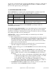
of the building. (see specific section for Home/Office, marine and RV installations) The omni-directional antenna should be installed on the side of the building with the strongest cellular signal as indicated by the bars on the cell phone. The outside antenna must be installed outside of the building, RV or boat. The inside antenna must be mounted in a central location in the building that is 40’ or greater from the outside antenna. The inside and outside antenna also must be separated by an exterior wall.
To plug into a standard 110 VAC receptacle use P/N DP255, a 110 VAC to 5VDC Power Supply. For use on a boat or RV, plug P/N DP515, a 12 VDC to 5 VDC Power Cable, into a 12 VDC cigarette style power receptacle. d. AMPLIFIER/REPEATER STATUS The DA4000SBR unit is designed with a status/fault indicator to indicate proper unit functionality. The chart below details the different LED color indicators.
e. IN-BUILDING COVERAGE PROBLEMS If the DA4000SBR unit does not indicate a red light and the coverage area appears to be smaller than anticipated, one or more of the following may limit the signal strength to the area. • Cell Phone Bars - The bars on the cell phone do not indicate coverage area. One bar may be adequate to successfully place and receive calls. Test coverage area by successfully completing calls while disregarding bar indicator.
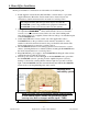
4. Home/Office Installation Review pre-installation considerations and determine site installation plan. 1. Install supplied outside antenna (P/N 288-PB) to vertical surface or pole with supplied hardware. Mount the outside antenna clear of metal objects and obstructions. Outside antenna must be mounted in a vertical position. WARNING! Only Digital Antenna authorized products may be used with the DA4000SBR system.
5. Marine Installation Review pre-installation considerations and determine site installation plan. 1. Install supplied outside antenna (P/N 288-PB) to vertical surface or pole with supplied hardware. Mount the outside antenna clear of metal objects and obstructions and as high as possible. Outside antenna must be mounted in a vertical position. The DA4000SBR system may also be used with one of Digital Antenna’s marine 9dB gain dual band cellular antennas.
6. RV Installation Review pre-installation considerations and determine site installation plan. 1. Install supplied outside antenna (P/N 288-PB) to vertical surface or pole with supplied hardware. Outside antenna must be mounted in a vertical position. Mount the outside antenna clear of metal objects and obstructions and as high as possible but take care not to exceed height of other roof mounted items such as A/C. WARNING! Only Digital Antenna authorized products may be used with the DA4000SBR system.
7. Specifications Amplifier/Repeater Unit P/N DA4000SBR • Frequency: Uplink: 824-849 MHz and 1850-1910 MHz Downlink: 869-895 MHz and 1930-1990 MHz • Modulations: AMPS/GPRS/TDMA/PCS/CDMA/GSM850/GSM1900 • Max Output Power: 3W (824-849 MHz), 2W (1850-1910 MHz) • Dynamic Variable Gain: 60dB Max • Impedance: 50 ohms • Noise Figure: < 10dB • Power Consumption: Standby 5 vdc/0.5A, Uplink 5 vdc/1.
Cable • • • • • P/N DA340-50NM Length: 50’ Impedance: 50 Ohm RF connectors: N male and mini-UHF male factory attached Attenuation at 800 MHz: 2.5 dB per 30’ Attenuation at 1900 MHz: 5.5 dB per 30’ Power Supply P/N DP255 • Input: 100-240VAC 50/60 Hz • Output: 5VDC 1.5A • Mounting: Wall type • Cord Length: 10’ (3m) • Output plug: 5.5 x 2.5 x 11mm Power Cable P/N DP515 • Input: +/- 9VDC to +/- 24 VDC • Output: 5VDC 1.
Ferrule for mounting P/N 288-PB on 1”x14 male threads 2-way Cellular Combiner w/ mini-UHF female connectors Dash/wall mount adapter cable 5’ length F114 (available 7/01/04) DA-2100 C428-05 Digital Antenna manufacturers cellular amplifiers, repeaters and antennas for the best communication on land or sea. All products are designed, engineered and manufactured by Digital Antenna in the USA. Visit www.DigitalAntenna.com to view our complete product line. 9.