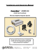
Installation and Operation Manual PowerMaxTM 4KSBR-50U 60 dB Gain Dual Band Wireless Amplifier/Repeater System Read Instructions before installing! If you do not understand instructions, seek professional installation. D IGITA L AN TEN N A >Digital Antenna, Inc. >5325 NW 108th Avenue >t 954.747.7022 >www.digitalantenna.com >Sunrise, FL 33351 >f 954.747.
INSTALLATION AND OPERATION MANUAL Model #4KSBR-50U 1. Package Contents……………………………………………………………….…….. 3 2. Important Safety Information………………………………………………………… 3 a. Limited Warranty………………………………………………….……. 4 b. Limitation on Liability…………………………………………….…….. 4 c. FCC Regulations………………………………………………………… 4 3. Pre-installation Guidelines……………………………………………………………. 5 a. Installation Tools…………………………………………………...…… 5 b. Installation Procedure………………………………………….……..…. 5 c. Electrical Power…………………………………….………………….... 6 d.
IMPORTANT Read instructions completely before attempting install! 1.
a. LIMITED WARRANTY Digital Antenna, Inc. warrants marine antennas for five (5) years and cellular antennas and amplifiers for one (1) year that its Products sold hereunder will at the time of shipment be free from defects in material and workmanship and will conform to Digital Antenna’s applicable specifications or, if appropriate, to Customer’s specifications previously accepted by Digital Antenna in writing.
3. Pre-Installation Guidelines a. INSTALLATION TOOLS The following tools are required for installation: • Standard wrench and philips head screwdriver • Standard drill with ½” bit (optional) • Cellular phone operating on 800 or 1900 MHz bands (any USA or Canadian cellular phone except Nextel) • Wire fasteners (optional) • Multi-meter for testing electrical continuity and AC and DC line voltage (for troubleshooting only) b.
of the building. (see specific section for Home/Office, marine and RV installations) The omni-directional antenna should be installed on the side of the building with the strongest cellular signal as indicated by the bars on the cell phone. The inside antenna must be mounted in a central location in the building, RV or boat that is 40’ or greater from the outside antenna with as much vertical separation as possible. Vertical separation is better than horizontal.
To plug into a standard 110 VAC receptacle use PN DP255, a 110 VAC to 5VDC Power Supply. For use on a boat or RV, plug PN DP515, a 12 VDC to 5 VDC Power Cable, into a 12 VDC cigarette style power receptacle. The 12 VDC power supply has a micro-processor controller to turn the repeater off if not properly installed. If a red flashing light appears on the power supply, relocate the inside and outside antennas until the power supply and repeater have a constant green light.
• If the outside and inside antennas are separated by 40’ or more and an exterior wall, the red light may be indicating the use of analog phones. Contact Digital antenna if you are using an analog phone. No light on Repeater – indicates improper installation and the power supply is stopping power to the repeater or no power is available.
f. COAXIAL CABLE RECOMMENDATIONS The 4KSBR-50U system includes 50’ of Digital Antenna’s PowerMaxTM ULTRA low loss cable and connectors for easy installation. If the installed application requires more than the supplied cable, PowerMaxTM DA340 ULTRA low loss 25’ extension cable and 75’ replacement cable are available. Only Digital Antenna authorized cable can be used to complete the installation. Unauthorized cable usage can be detected and voids the warranty.
4. Home/Office Installation Review pre-installation considerations and determine site installation plan. 1. Install supplied outside antenna (PN 288-PW) to vertical surface or pole with supplied hardware. Mount the outside antenna clear of metal objects and obstructions. Outside antenna must be mounted in a vertical position. Antennas must be separated by a structure and a 40’ or greater distance with as much vertical separation as possible. Vertical separation is better than horizontal.
5. Marine Installation Review pre-installation considerations and determine site installation plan. 1. Install supplied outside antenna (PN 288-PW) to vertical surface or pole with supplied hardware. Mount the outside antenna clear of metal objects and obstructions and as high as possible. Use PN F114 to mount 288-PW to 1”-14 threaded basse. Outside antenna must be mounted in a vertical position.
6. RV Installation Review pre-installation considerations and determine site installation plan. 1. Install supplied outside antenna (PN 288-PW) to vertical surface or pole with supplied hardware. Outside antenna must be mounted in a vertical position. Mount the outside antenna clear of metal objects and obstructions and as high as possible but take care not to exceed height of other roof mounted items such as A/C. The base of the antenna only can be attached or next to metal.
7. Specifications Amplifier/Repeater Unit PN DA4000SBR • Frequency: Uplink: 824-849 MHz and 1850-1910 MHz Downlink: 869-895 MHz and 1930-1990 MHz • Modulations: ALL • Max Output Power: 3W (824-849 MHz), 2W (1850-1910 MHz) • Dynamic Variable Gain: 64dB Max • Impedance: 50 ohms • Noise Figure: < 10dB • Power Consumption: Standby 5 vdc/0.5A, Uplink 5 vdc/1.5A • Internal Fuse: 3A • FCC approved, FCC ID: PZODA4000SBR • Industry Canada approved, IC ID: 4260A-DA4000SBR • Dimensions: 4.5" l x 4.0" w x 1.
Cable • • • • • PN 340-50NM Length: 50’ Impedance: 50 Ohm RF connectors: Type N male and mini-UHF male factory attached Attenuation at 800 MHz: 5.7dB per 100’ Attenuation at 1900 MHz: 8.5dB per 100’ Power Supply PN DP255 • Input: 100-240VAC 50/60 Hz • Output: 5VDC 1.5A • Mounting: Wall type • Cord Length: 10’ (3m) • Output plug: 5.5 x 2.5 x 11mm Power Cable PN DP515 • Input: 9VDC to 24 VDC • Output: 5VDC 1.5A • Connector: Cigarette lighter style • Internal fuse: 3A • Cord Length: 76” (1.
8. Antenna & Accessory Options For complete specifications Visit www.DigitalAntenna.com Omni-directional Cell Antennas (Outside) White PN Black PN 2.5' Dual Band 9dB Gain Cellular Antenna w/ male 1"-14 4' Dual Band 9dB Gain Cellular Antenna w/ male 1"-14 8' Dual Band 9dB Gain Cellular Antenna w/ male 1"-14 2.
9. Technical Support For answers to most questions access Digital Antenna’s knowledgebase and Troubleshooter section on Digital Antenna’s website www.DigitalAntenna.com. When contacting Digital antenna regarding your repeater, locate the product’s serial number on the DA4000SBR unit before calling. The serial number is located on the bottom of the DA4000SBR unit. The DA4000SBR serial number must be available to authorize technical support and/or establish a return authorization.