
User`s manual


18
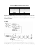
from a concealed microphone that has interfering radio/TV audio. The RIGHT (REF) input is the
noise reference, usually the audio output from a second radio/TV tuned to the same channel.
The signals are first fed through the stereo Limiter, which helps prevent the signals from distorting
on overload. The Limiter internally “links” the two channels, such that an overload on either input
channel will cause the levels to be reduced equally on both channels. This minimizes the impact on
the 2CH Adaptive filter solution.
The limited signals then enter the first stage 2CH Adaptive filter, which is configured as follows:
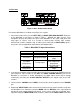
Table 4: 2CH MODE First Stage Factory Presets
Parameter Preset Value
Filter Size 3472 taps
Delay Channel Input (Primary)
Delay 100 samples
Adapt Rate 16
Adapt Mode Auto
Output Residue
Algorithm LMS
Reference Compensation Enabled
Crash Detect Enabled
After the first stage of filtering, the signal enters the second stage 1CH Adaptive filter, which is
configured as follows:
Table 5: 2CH MODE Second Stage Factory Presets
Parameter Preset Value
Filter Size 128 taps
Prediction Span Delay 2 samples
Adapt Rate 32
Adapt Mode Auto
Output Residue
Algorithm LMS
Crash Detect Enabled
Next, the signal is 200Hz Highpass filtered, to remove any low frequency noises that may remain
after processing, and 3200Hz Lowpass filtered to remove high frequency hiss.
Finally, a 10dB AGC is applied to correct for near party / far party talkers, and to provide a good
output level for recording.