MicroDAC IV PORTABLE PROGRAMMABLE DIGITAL FILTER CONFIGURATION SOFTWARE USER’S MANUAL DIGITAL AUDIO CORPORATION A DRI COMPANY
MicroDAC IV PORTABLE PROGRAMMABLE DIGITAL FILTER CONFIGURATION SOFTWARE User’s Manual March 31, 2003 Document Number: 990398 Version 1.0 DIGITAL AUDIO CORPORATION A DRI COMPANY 5121 Holly Ridge Drive Raleigh, NC 27612 Phone: 919 782 6767 Fax: 919 782 6766 sales@dacaudio.com www.dacaudio.com Copyright © 1999 by Digital Audio Corporation. All rights reserved.
TABLE OF CONTENTS 1. OVERVIEW ..................................................................................................................................................... 2 1.1 Introduction ............................................................................................................................................... 2 2. INSTALLATION............................................................................................................................................... 4 2.
8. ADJUSTING MAXIMUM TAPS FOR EACH STAGE............................................................................................
LIST OF FIGURES Figure 3-1 MicroDAC IV Control Panel .................................................................................................................... 5 Figure 3-2 Input Limiter Controls............................................................................................................................. 6 Figure 3-3 Highpass Filter.......................................................................................................................................
1
1. OVERVIEW 1.1 Introduction The MicroDAC IV Configuration Software allows for complete setup and control of the three preset adaptive filters and four configurable filters, each consisting of up to two stages. The software provides an easy to use, intuitive interface for configuring the filter settings and transferring them to the MicroDAC IV.
3
2. INSTALLATION 2.1 Software Requirements This Windows software-based product consists of an installation CD, User’s manual, and communications cable. Supported operating systems include Windows 95/98/ME/2000/NT/XP. The PC should have the following minimum capabilities: Ø Ø Ø Ø Ø 200MHz Pentium III processor 32MB RAM 10 MB of free hard disk space storage CD-ROM drive for installing the software 800x600 resolution SVGA monitor 2.
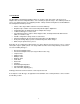
3. MICRODAC IV CONFIGURATION CONTROL PANEL 3.1 MicroDAC IV Control Panel Figure 3-1 MicroDAC IV Control Panel At the top of the MicroDAC IV Control Panel is a Menu Bar. From the File menu, you can choose to create a New2 filter configuration, Open a filter configuration file, Save a file As a different or similar file name, Program the MicroDAC IV, adjust the Panel Lock Settings to be programmed, use the Utilities to directly control the panel lock settings, select a COM Port, or Exit the software.
• Mono Single configures the MicroDAC IV to apply a single large stage (Stage 1) of filtering to the Left Input only. When using the 2CH Adaptive filter, the Right Input is used as the cancellation reference. The output of Stage 1 is routed to both the Left and Right Outputs. • Mono Series configures the MicroDAC IV to split its filtering resources among two smaller stages (Stage 1 and 2), applying them in series to the Left Input.
3.4 Input or Output Highpass Filter The Highpass Filter controls are shown in Figure 3-3. The 200 Hz Highpass Filter is used to remove any low frequency noises that may need to be removed before processing (“Input HPF”) or after processing (“Output HPF”). Selecting “No HPF” will disable this feature. This filter is separate from the Highpass Filter described in Appendix A, and has no adjustable parameters. Figure 3-3 Highpass Filter 3.
The MicroDAC IV Configuration Software allows the front panel controls to be locked to prevent accidental tampering by nontechnical operators. This feature is useful when the MicroDAC IV is deployed in a tactical setting. There are three locking options, described as follows: 3.7.1 • No Lock: This option unlocks all the front panel controls, allowing the user to adjust the input levels and select any filtering mode via the MODE switch.
Figure 3-7 Panel Lock Settings Windows The lock setting to be programmed into the MicroDAC along with the filter settings can be selected by clicking on appropriate radio button in the “Panel Locked Mode” area of the window. When the Mode Switch Lock option is selected, the “Mode Switch Setting” area of the window will be enabled, allowing the desired MODE switch setting to be specified.
10
4. PROGRAMMING THE MICRODAC IV 4.1 Selecting the correct COM Port The COM Port menu option within the File menu allows you to select the COM Port on which the software will first attempt to communicate with MicroDAC IV when programming it. If you are unsure which COM Port your MicroDAC IV is connected to, then leave it set at the default option of COM 1, and the software will automatically search all COM Ports until the MicroDAC IV is found.
Figure 4-3: MicroDAC IV Transfer Window Programming of the MicroDAC IV can be stopped at any time by pressing the Cancel button. A message window may then appear to inform you that the download has been aborted and that the filters stored in MicroDAC IV are no longer valid. Because the download was stopped before it was completed, the filter settings stored in the MicroDAC IV may no longer be usable.
5. STORING FILTER CONFIGURATIONS 5.1 Save File Dialog Box Application: To save time configuring the MicroDAC IV control settings, complete setups may easily be stored to disk setup files for future recall. Store a setup to a disk file as follows: 1. Click on File on the MicroDAC IV menu bar. When the pulldown menu appears, click on Save As (or click on the "floppy disk" icon on the toolbar). This will cause the following window to appear: Figure 5-1: Save As Setup File Window 2.
14
6. RECALLING FILTER CONFIGURATIONS 6.1 Open File Dialog Box Application: To save time configuring control settings in the MicroDAC IV control settings, complete setups previously stored may be recalled from disk files with a few simple mouse clicks. Open a setup from a disk file as follows: 1. Click on File on the MicroDAC IV menu bar. When the pulldown menu appears, click on Open (or click on the "open file folder" icon on the toolbar).
16
7. FILTER CONTROL WINDOWS 7.1 One channel adaptive filter Application: The 1CH Adaptive filter is used to automatically cancel predictable and convolutional noises from the input audio. Predictable noises include tones, hum, buzz, engine/motor noise, and, to some degree, music. Convolutional noises include echoes, reverberations, and room acoustics.
rescaled depending upon the input signal level. Overall convergence rate is faster with Auto. Adapt Algorithm: Selects the adaptive algorithm to use when processing the audio. The Least Absolute Value (LAV) algorithm offers faster, but less accurate convergence. The Least Mean Square (LMS) algorithm does not converge as fast as the LAV, but offers a more accurate convergence and better maintains the final solution. Processor Output: Used to select the output of the filter.
Stopband Attenuation: Specifies amount in dB by which frequencies above the Cutoff Frequency are ultimately attenuated. Stopband attenuation is adjustable from 0dB to 90dB in 1 dB steps. Transition Slope: Specifies slope at which frequencies above the Cutoff Frequency are rolled off in dB per octave. Sharpest roll off occurs when Transition Slope is set to maximum, while gentlest roll off occurs when Transition Slope is set to minimum.
Description of controls is as follows: Cutoff Frequency: Specifies frequency in Hertz below which all signals are attenuated. Frequencies above this cutoff are unaffected. Minimum Cutoff Frequency is 100 Hz, while the maximum Cutoff Frequency is 5400 Hz. Cutoff Frequency can be adjusted in 1 Hz steps. Stopband Attenuation: Specifies amount in dB by which frequencies below the Cutoff Frequency are ultimately attenuated. Stopband attenuation is adjustable from 0dB to 90dB in 1 dB steps.
Figure 7-6: Bandpass Filter Control Window Description of controls is as follows: Lower Cutoff Frequency: Specifies frequency in Hertz below which all signals are attenuated. Frequencies between this cutoff and the Upper Cutoff Frequency are Unaffected. Minimum Lower Cutoff Frequency is 0 Hz, while the maximum Lower Cutoff Frequency is 100 Hz below the Upper Cutoff Frequency. Lower Cutoff Frequency can be adjusted in 1 Hz steps.
7.5 Bandstop Filter Application: The Bandstop filter is used to decrease the energy level (lower the volume) of all signal frequencies above a specified Lower Cutoff Frequency and below a specified Upper Cutoff Frequency. The signal region between the Lower Cutoff Frequency and the Upper Cutoff Frequency is called the stopband region. The Bandstop filter is useful for removing in-band noise from the input signal.
Frequency. Also, note that the Lower and Upper Transition Slopes always have different values; this is because the frequency width of an octave is proportional to Cutoff Frequency. Stopband Attenuation: Specifies amount in dB by which frequencies above the Lower Cutoff Frequency and below the Upper Cutoff Frequency are attenuated. Stopband attenuation is adjustable from 0dB to 90dB in 1 dB steps. A graphical description of the Bandstop filter and its controls follows in the figure below.
Notch Limit: Specifies frequency in Hertz above which no notches are generated. Minimum Notch Limit is 2 and 1/2 times the Fundamental Notch Frequency, while the maximum Notch Limit setting is 5400 Hz. Notch Limit is adjustable in 1 Hz steps. Notch Depth: Depth of notches that are generated. Notch Depth is adjustable from 0 dB to 90 dB in 1 dB steps. Notch Harmonics: Specifies whether notches will be generated at All, Odd, or Even multiples, or harmonics, of the Comb Frequency.
of the noise. This is best done by adjusting the Notch Frequency up or down 1 Hz at a time while listening to the Notch filter output on the headphones. Often, the noise frequency will not remain absolutely constant but will vary slightly due to modulation, recorder wow and flutter, and acoustic "beating." Therefore, you may need to increase the Notch Width from its minimum setting to keep the noise within the notch. For maximum noise reduction, set the Notch Depth to 90dB.
To properly utilize the Slot filter, you will first need to identify the frequency of the signal to be isolated; this is best done using a Spectrum Analyzer. Once the frequency of the signal has been identified, initially set Stopband Attenuation to 90 dB and the Slot Width to the narrowest possible value. Next, set the Slot Frequency to the signal frequency. Fine adjustment of the Slot Frequency may be necessary to place the slot right on top of the signal.
7.9 20-Band Graphic Equalizer Application: The 20-band Graphic Equalizer is an easy-to-use linear-phase FIR digital filter that is used to reshape the spectrum of the final output signal. Reshaping is accomplished with twenty vertical scroll bars (also called "slider" controls) which adjust the attenuation of each frequency band.
The Spectral Graphic Equalizer is essentially a 115-band graphic equalizer; however, instead of having 115 separate slider controls, it allows the user to precisely draw the desired filter shape on the computer screen, using the mouse, with as much or as little detail as desired.. The Edit feature allows the user to make readjustments to the filter shape, while the Normalize button allows the user to shift the entire filter curve up until the highest point is at 0dB.
To draw the new filter curve, you will need to carefully click the mouse cursor on points within the filter display area which correspond to the desired attenuations at the desired frequencies. While the mouse click button is held down, the Freq and Atten readouts will be updated as the mouse is moved; you can use this feature to place points in the filter curve at exact frequencies and attenuations.
In this window, you can make the entire filter curve drop by a specified amount prior to editing the curve. This can be used to create headroom which can be used to increase the gain (decrease the attenuation) in one portion of the curve relative to the rest of the curve. For now, select a drop of 0dB (No Drop) and click on Proceed. 7. You should now notice that all the buttons on the control window have been replaced with a single Abort button, which permits returning to the pre-Edit filter.
Figure 7-25: Normalized Spectral Graphic Equalizer This completes the Spectral Graphic Equalizer mini-tutorial. 7.11 Imported Coeffecient File Application: The Imported Coefficient file is available for inputing filters created via other synthesis software. Several math software packages (such as Matlab) are available from other vendors. These packages provide high level math functions for computing complex filters.
0.0008975 Scientific notation is in the form: mantissaE[+-]exponent The following are some examples of floating point coefficients in scientific format: 3.25E-003 5.36E-2 1.25E-004 8.1234E2 = = = = 0.003250 0.0536 0.000125 812.34 (clipped to +1.0 by the MicroDAC IV software) Only one coefficient may be located on a line. The coefficients can be comma-separated, but must still be stored on to a line. The MicroDAC IV only uses the maximum number of coefficients available for each stage.
-7.269745E-002 -5.050633E-002 8.298883E-003 4.286449E-002 2.956892E-002 -8.256326E-003 -3.074622E-002 -1.991908E-002 8.196839E-003 2.407519E-002 1.430844E-002 -8.120655E-003 -1.978514E-002 -1.060535E-002 8.028165E-003 1.674714E-002 7.957611E-003 -7.919611E-003 -1.444848E-002 -5.957981E-003 7.795490E-003 1.262311E-002 4.387280E-003 7.
Figure 7-28 Two Channel Adaptive Filter Control Window Description of controls (Figure 7-28) is as follows: Filter Size: Used to set the number of FIR filter taps in the adaptive filter. Filter size is indicated both in taps (filter order) and in milliseconds. Minimum Filter Size is 16 taps, but can be set to as high as 3600 (Mono Single mode, see Section A-8. ).
8. ADJUSTING MAXIMUM TAPS FOR EACH STAGE A feature available on the MicroDAC IV is the ability to trade filter taps between stages in Mono Series mode when one of the filters is an adaptive filter. To adjust the number of taps available, first display the control screen for the adaptive filter in the Mono Series configuration. If the Stage Mode is Mono Series the Adjust Maximum Size button will be displayed within the Filter Size section of the control screen (see Figure 8-1).
36
37