
User`s manual


6
• Mono Single configures the MicroDAC IV to apply a single large stage (Stage 1) of filtering to the
Left Input only. When using the 2CH Adaptive filter, the Right Input is used as the cancellation
reference. The output of Stage 1 is routed to both the Left and Right Outputs.
• Mono Series configures the MicroDAC IV to split its filtering resources among two smaller stages
(Stage 1 and 2), applying them in series to the Left Input. When using the 2CH Adaptive filter, the
Right Input is used as the cancellation reference (the 2CH Adaptive filter is only available on
Stage 1.) The output of Stage 1 is routed to the input of Stage 2, and the output of Stage 2 is
routed to both the Left and Right Outputs.
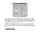
• Stereo Linked configures the MicroDAC IV to apply the two stages (Stage 1 and 2) to a stereo
signal. The Left Input is routed through Stage 1 and the Right Input is routed through Stage 2.
The outputs of Stage 1 and 2 are routed to the Left and Right Outputs, respectively. The 2CH
Adaptive filter is not available with the Stereo Linked option. The Stage 2 filter is identical to
Stage 1; any changes made to the settings of Stage 1 will also be applied to Stage 2.
The stages can implement any of the following filter types:
• One Channel Adaptive Filter
• Lowpass Filter
• Highpass Filter
• Bandpass Filter
• Bandstop Filter
• Comb Filter
• Notch Filter
• Slot Filter
• 20 Band Graphic Equalizer
• Spectral Graphic Equalizer
• Imported Coefficient File
• Two Channel Adaptive Filter
3
• Pass Thru Filter
Once the filter type is selected, click on the Control button to bring up the control window for that filter.
This window allows you to customize the parameters for desired filter performance. After selecting the
values for each parameter, click on the OK button.
Refer to Appendix A for more information on the filter types and full explanations of their parameters.
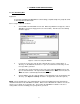
3.3 Input Limiter
The Input Limiter controls are shown in Figure 3-2. The Input Limiter helps prevent the input signals
from distorting on overload and is “linked” so that an overload on either input channel will cause the levels
to be reduced equally on both input channels. Selecting the “Limiter In” radio button will enable the Input
Limiter for the filter setup, while “Limiter Out” will disable this feature.
Figure 3-2 Input Limiter Controls
3
Not available in Stage 2