
User`s manual


21
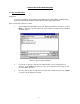
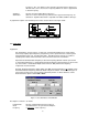
Figure 7-6: Bandpass Filter Control Window
Description of controls is as follows:
Lower Specifies frequency in Hertz below which all
Cutoff signals are attenuated. Frequencies between this
Frequency: cutoff and the Upper Cutoff Frequency are Unaffected. Minimum Lower Cutoff
Frequency is 0 Hz, while the maximum Lower Cutoff Frequency is 100 Hz below the
Upper Cutoff Frequency. Lower Cutoff Frequency can be adjusted in 1 Hz steps.
NOTE: The Lower Cutoff Frequency can never be set higher than 100 Hz below the
Upper Cutoff Frequency.
Upper Specifies frequency in Hertz above which all
Cutoff signals are attenuated. Frequencies between this
Frequency: cutoff and the Lower Cutoff Frequency are unaffected. Minimum Upper Cutoff
Frequency is 100 Hz above the Lower Cutoff Frequency, while the maximum Upper
Cutoff Frequency is 5400 Hz. Upper Cutoff Frequency can be adjusted in 1 Hz
steps.
NOTE: The Upper Cutoff Frequency can never be set lower than 100 Hz above the
Lower Cutoff Frequency.
Transition Specifies slope at which frequencies below the
Slope: Lower Cutoff Frequency and above the Upper Cutoff Frequency are attenuated in
dB per octave. Sharpest attenuation occurs when Transition Slope is set to
maximum, while gentlest attenuation occurs when Transition Slope is set to
minimum. Note that the indicated value changes depending upon Cutoff Frequency.
Also, note that the Lower and Upper Transition Slopes always have different values;
this is because the frequency width of an octave is proportional to Cutoff Frequency.
Stopband Specifies amount in dB by which frequencies below
Attenuation: the Lower Cutoff Frequency and above the Upper Cutoff Frequency are ultimately
attenuated. Stopband Attenuation is adjustable from 0dB to 90dB in 1 dB steps.
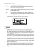
A graphical description of the Bandpass filter and its controls follows in the figure below.
Figure 7-7: Bandpass Filter Graphical Description