
User's Manual


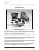
Table Of Contents
- Safety Precautions and Warnings
- Dear Customer:
- Introduction
- F Series Battery Charger System
- Receiver
- General Description
- Standard Receiver Display Screen Symbols
- /Power On
- Power Off
- Automatic Shutdown
- Toggle & Trigger Switches
- Audible Tones
- Main Menu
- /Calibration Menu
- /Height-Above-Ground (HAG) Menu
- /Settings Menu
- Transmitter Selection Menu
- /DigiTrak LWD (Log While Drilling) Menus
- Target Steering Menu
- Using the Keypad
- Display Screens
- Transmitter
- Remote Display
- Locating
- The Target Steering Function
- Appendix A: System Specifications and Maintenance Requirements
- Appendix B: Projected Depth Versus Actual Depth and the Fore/Aft Offset
- Appendix C: Calculating Depth Based on Distance Between FLP and RLP
- Appendix D: Reference Tables
- Appendix E: EU Required Documentation
- LIMITED WARRANTY

Introduction
10 DigiTrak
®
F5
®
Operator’s Manual
The F5 system is programmed to comply with varying global operating requirements. The receiver’s
regional designation number must match that of the transmitter for proper communication (see Receiver
and Transmitter sections). Also, the receiver’s telemetry frequency designation must match that of the
remote display (see Receiver and Remote Display sections).
Appendix A presents the F5 system’s power, environmental, and maintenance requirements. Appendix B
explains how to calculate depth when the transmitter is deep (greater than 15 ft or 4.6 m) and/or at a
steep pitch (greater than ±30% or ±17°). Appendix C explains how to calculate the transmitter depth
based on the distance between the front and rear locate points and the pitch of the transmitter. Appendix
D provides calculated depth increases for 10-ft (3-m) and 15-ft (4.6-m) rods depending on pitch. Finally,
Appendix E contains a list of the radio frequency restrictions for each country in the EU and the required
declaration of conformity documents.