MFCB Multi-Function Cable Box Operator’s Manual DIGITAL CONTROL INCORPORATED DCI Europe Kurmainzer Strasse 56 D-97836 Bischbrunn Germany Tel +49(0) 9394 990 990 Fax +49(0) 9394 990 999 DCI.Europe@digital-control.com DCI India DTJ 1023, 10th Floor DLF Tower A, DA Dist. Cent. Jasola, New Delhi 110044 India Tel +91(0) 11 4507 0444 Fax +91(0) 11 4507 0440 DCI.India@digital-control.com DCI China No. 41, Lane 500, Xingle Road Huacao Town, Minhang District Shanghai P.R.C.
DIGITAL CONTROL INCORPORATED 3-3400-00-A1 © 2010 by Digital Control Incorporated. All rights reserved. March 2011 edition. Trademarks 68B ® ® ® ® ® ® ® ® ® The DCI logo, CableLink , DataLog , DigiTrak , Eclipse , F2 , iGPS , MFD , SST , target-in-the-box , ® ® Target Steering , and TensiTrak are U.S. registered trademarks and DucTrak™, F Series™, FSD™, FasTrak™, LT™, LT2™, SE™, SuperCell™, and TeleLock™ are trademarks of Digital Control Incorporated.
DIGITAL CONTROL INCORPORATED Table of Contents TABLE OF CONTENTS ................................................................................................................................ 3 Dear Customer: ......................................................................................................................................... 6 SAFETY PRECAUTIONS AND WARNINGS.................................. ERROR! BOOKMARK NOT DEFINED. MULTI-FUNCTION CABLE BOX ........................................
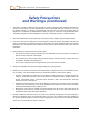
DIGITAL CONTROL INCORPORATED Safety Precautions and Warnings Important Note: All operators must read and understand the following Safety Precautions and ® ® Warnings and must review this Operator’s Manual before using the DigiTrak F2 Locating System. Serious injury and death can result if underground drilling equipment makes contact with an underground utility such as a high-voltage electrical cable or a natural gas line.
DIGITAL CONTROL INCORPORATED Safety Precautions and Warnings (Continued) The battery charger provided with the DigiTrak F2 system is designed with adequate safeguards to protect you from shock and other hazards when used as specified within this document. If you use the battery charger in a manner not specified by this document, the protection provided may be impaired. Do not attempt to disassemble the battery charger. It contains no user-serviceable parts.
DIGITAL CONTROL INCORPORATED Dear Customer: Thank you for choosing DigiTrak® Locating Systems. We are proud of the equipment that we have been designing and building in Washington State since 1990. We believe in providing a unique, high-quality product and standing behind it with superior customer service and training. Please take the time to read this entire manual—especially the section on safety.
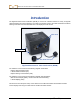
DIGITAL CONTROL INCORPORATED Introduction The DigiTrak Multi-Function Cable Box (MFCB) is used as an interface between a variety of DigiTrak cable transmitters and remote displays. The cable box provides power to the cable transmitter and allows steering information from the transmitter wire to be displayed on the remote.
Power Setup Notes 8 ® DigiTrak MFCB™ Operator’s Manual
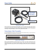
DIGITAL CONTROL INCORPORATED Power Setup The cable box has two identical power ports shown in the introduction. The ports can be used interchangeably; one needs to be connected to the DC power source and the other to the remote display’s DC power port. The power ports are keyed to match the power cable connectors. The power cables are installed in the same way as the remote display’s standard DC power cable.
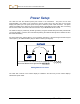
Power Setup Connects to the DC Power Source (or use the bare wire cable to connect directly to a freestanding automotive battery) Connects to the Remote Display’s DC Power Port Cable-Box Power Cables When connecting to a free standing automotive battery, be sure the positive wire (white, shown red in the Connecting the Cable System Components diagram below) is connected to the positive battery terminal and that the negative wire (black) is connected to the negative battery terminal.
Multi-Function Cable Box Once the ground connection is achieved, the cable transmitter is powered through the DCI cable-box as shown below. Cable to Transmitter Knob Power Post SST Serial Cable Port Cable Transmitter Powered through Cable-Box Install the cable from the transmitter by rotating the knob on the cable-box counterclockwise until the hole in the power post is exposed. Insert the stripped portion of the cable into the hole and gently tighten the knob by rotating it clockwise to secure.
Power Setup Connecting Cable System Components The compression fitting shown in the diagram above is a non-DCI part required to seal the transmitter from the drilling fluid. Drill or tooling manufacturers will have information on compression fittings.
DIGITAL CONTROL INCORPORATED Cable Mode Display Screens The standard Eclipse and F-Series Cable modes and the Eclipse SST mode display screens are viewed by selecting the cable icon on the main menu of the MFD or FSD remote display. The cable system components must be properly connected with power supplied before you can access this menu option. Main Menu with Cable Mode Highlighted The remote will automatically detect which cable system is being used and display the appropriate screen.
Cable Mode Transmitter Pitch Empty update meter indicates no telemetry reception Transmitter Roll Output voltage and current (Amperage) supplied by the Cable-Box Input voltage range (approximate) supplied to the transmitter Eclipse and F-Series Cable Mode Main Display The above screen shows no telemetry data being received as indicated by the empty update meter. The roll and pitch are provided through the cable.
Cable Mode remote will display the transmitter’s heading or “yaw” at the bottom of the screen, shown above. The reference yaw must be programmed to this value. Program the reference yaw in the Reference Yaw Menu as described below. Reference Yaw Menu From the Eclipse SST Main Display, press the up direction button, the Reference Yaw Menu.
Cable Mode Numbers for the reference yaw display here as they are entered Backspace deletes the last number entered Curved arrow (Execute) sets the reference yaw “Exit” (highlighted) exits the menu with no change Reference Yaw Manual Entry Key Pad Enter the reference yaw value in this screen by using the direction buttons to highlight a number and the execute button to select it. Enter the value for reference yaw one digit at a time left to right; then select the curved arrow to set it.
Cable Mode Target Steering When a target depth has been programmed into the receiver and the remote is receiving telemetry data, the following screen will display. Actual SST Yaw SST’s Deviation from Reference Yaw SST Target Steering Display If a standard Eclipse Cable transmitter is used, the screen will display as above but without the yaw data and the roll will display by clock position as opposed to the 360⁰ indicator shown here. See the Target Steering Display in the Remote Mode section.
Cable Mode Fixed mark denoting drill head’s 12 o’clock position Transmitter’s 12 o’clock position “Go” activates roll offset to the value most recently set “Set” programs the displayed value as the roll offset Exit (highlighted) exits the menu with no change Roll Offset Menu (Enable) There are three options in the roll offset menu as described above. Use the direction buttons to highlight the desired option and the execute button to select it.
Cable Mode “Stop” disables the roll offset “Set” programs the displayed value as the roll offset Exit (highlighted) exits the menu with no change Roll Offset Menu (Disable or Set) Selecting will disable roll offset and return you to the standard cable or SST mode display screen. The value displayed for roll will be that of the transmitter. Selecting “Set” will program the roll offset to the displayed value.
Cable Mode Notes 20 ® DigiTrak MFCB™ Operator’s Manual
DIGITAL CONTROL INCORPORATED Appendix A: System Specifications and Maintenance Requirements The power requirements and environmental requirements for the DigiTrak Multi-Function Cable Box and remote displays are listed below. Power Requirements Device (Model Number) Operational Voltage (nominal) Operational Current DigiTrak Multi-Function Cable Box 12 - 28 V 6 A max DigiTrak MFD Remote Display (MFD) 14.4 V (nominal) 220 mA max DigiTrak F Series Remote Display (FSD) 14.
DIGITAL CONTROL INCORPORATED 19625 62nd Ave. S., Suite B-103 Kent, WA 98032 USA (425) 251-0559 OR (800) 288-3610 FAX (253) 395-2800 www.digitrak.com (Web Site) DCI@digital-control.
DCI reserves the right to make changes in design and improvements upon DCI Products from time to time, and User understands that DCI shall have no obligation to upgrade any previously manufactured DCI Product to include any such changes.