SE ™ Directional Drilling Locating System Operator’s Manual DIGITAL CONTROL INCORPORATED DCI Europe Kurmainzer Strasse 56 D-97836 Bischbrunn Germany Tel +49(0) 9394 990 990 Fax +49(0) 9394 990 999 DCI.Europe@digital-control.com DCI India SCO # 259, Sector 44-C Chandigarh (UT) 160 047 Punjab, India Tel +91(0) 172 464 0444 Fax +91(0) 172 464 0999 DCI.India@digital-control.com DCI China No. 41, Lane 500, Xingle Road Huacao Town, Minhang District Shanghai P.R.C.
DIGITAL CONTROL INCORPORATED 3-4200-00-A © 2009 by Digital Control Incorporated. All rights reserved. October 2009. Trademarks 68B ® ® ® ® ® ® ® ® ® The DCI logo, CableLink , DataLog , DigiTrak , Eclipse , F2 , iGPS , MFD , SST , target-in-the-box , ® ® Target Steering , and TensiTrak are U.S. registered trademarks and DucTrak™, F Series™, FSD™, SE™, FasTrak™, LT™, LT2™, SuperCell™, and TeleLock™ are trademarks of Digital Control Incorporated.
DIGITAL CONTROL INCORPORATED Table of Contents SAFETY PRECAUTIONS AND WARNINGS................................................................................................ 5 DEAR CUSTOMER: ...................................................................................................................................... 7 INTRODUCTION........................................................................................................................................... 9 RECEIVER ...................
DIGITAL CONTROL INCORPORATED Table of Contents (Continued) BATTERY CHARGER ................................................................................................................................. 41 General Description ................................................................................................................................. 41 Power Setup ..........................................................................................................................................
DIGITAL CONTROL INCORPORATED Safety Precautions and Warnings Important Note: All operators must read and understand the following Safety Precautions and ® Warnings and must review this Operator’s Manual before using the DigiTrak SE™ Locating System. Serious injury and death can result if underground drilling equipment makes contact with an underground utility such as a high-voltage electrical cable or a natural gas line.
DIGITAL CONTROL INCORPORATED Safety Precautions and Warnings (Continued) The battery charger provided with the DigiTrak SE system is designed with adequate safeguards to protect you from shock and other hazards when used as specified within this document. If you use the battery charger in a manner not specified by this document, the protection provided may be impaired. Do not attempt to disassemble the battery charger. It contains no user-serviceable parts.
DIGITAL CONTROL INCORPORATED Dear Customer: Thank you for choosing the Signature Edition DigiTrak® SE™ Locating System, which is exemplary of our commitment to the industry and the people in it. This system is named in honor of Steve Edwards, a pioneer in the horizontal directional drilling industry and an integral component to our success and to the success of a number of drilling companies worldwide. Steve passed away in late 2007 after a two year battle with pancreatic cancer.
DIGITAL CONTROL INCORPORATED Notes 8 ® DigiTrak SE™ Operator’s Manual
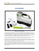
DIGITAL CONTROL INCORPORATED Introduction Receiver Battery Charger System ST Transmitter DigiTrak SE Locating System The DigiTrak SE Locating System is used during horizontal directional drilling operations to locate and track a transmitter installed in the drill head. You can use your existing DigiTrak Mark Series remote, MFD (Multi-Function Display) remote, or FSD (F Series Display) remote to view the transmitter data at the drill rig.
Introduction The SE system is programmed to comply with varying global operating requirements. The receiver’s regional designation number must match that of the transmitter for proper communication (see figure showing startup screen in Receiver section and photo of ST transmitter in Transmitter section). Also, the receiver’s telemetry frequency designation must match that of the remote display being used. Appendix A presents the SE system’s power, environmental, and maintenance requirements.
DIGITAL CONTROL INCORPORATED Receiver Display Screen Grip Handle Trigger Switch Battery Tab Battery Compartment Front Panel Boot SE Receiver – Side View General Description The SE receiver is a handheld unit used for locating and tracking an SE transmitter. The receiver converts signals from the transmitter and displays the following transmitter information: depth, pitch, roll, temperature, and battery level. The SE receiver then sends this information to the remote display at the drill rig.
Receiver Power On/Off Installing and Removing the Battery Pack Insert a fully charged DCI NiMH or lithium-ion battery pack so that it is flush with the back of the receiver and the tab is securely latched, as shown below. If necessary, push on the battery pack to latch the tab in place. Tab Inserting Battery Pack Battery Pack Fully Inserted Removing Battery Pack To remove the battery pack, push down on the battery tab and pull it away from the unit until the tab is released.
Receiver Next, click the trigger to check the box on the warning screen acknowledging that you have read and understand this manual. You must read this entire manual before using the SE system for any directional drilling procedure. The self-test will automatically initiate after the checkmark is displayed in the box. The self-test is performed every time the receiver is powered on. The following screen will display indicating a successful self-test.
Receiver From the startup screen, click the trigger to continue to the locate mode screen. When there is not a powered-up transmitter in the area, the screen will appear as shown below. The signal search symbol will display as the receiver searches for the transmitter's signal as shown below.
Receiver Trigger Switch The SE receiver operates with a single trigger switch. The trigger switch is used to turn on the unit, adjust the screen contrast, access and select menu options, as well as to change the screen view for depth measurements. Clicking the trigger versus holding the trigger will result in different actions. Click – Quickly pulling and releasing the trigger (in less than 1 second).
Receiver Receiver Battery Status (Shown 80% Full) Height-Above-Ground (HAG) Menu Telemetry Channel Menu (Channel 2 Selected) Box around item indicates it is highlighted for selection. Units & Roll Offset Menu Power Off Remote Steering Menu Calibration Menu Programmed Reference Depth Receiver Main Menu Screen The main menu screen also displays the receiver battery status and the current telemetry channel selection (channel 2 is shown in the example above).
Receiver Height-Above-Ground (HAG) Menu The HAG menu has three options: Turn On, Turn Off, and Set. Set allows you to change the current height setting. Clicking the trigger advances through each option, and holding the trigger in selects the option displayed. The default setting for the HAG function is off. Until you turn on or set a new HAG, the receiver must be placed on the ground for accurate depth readings.
Receiver Turn Off HAG The turn off HAG menu option shows the SE receiver on the ground. Turn Off HAG Screen Hold the trigger in to turn off the HAG function. You will hear the confirmation signal, and a checkmark will appear next to the receiver to indicate that the HAG has been successfully turned off. The receiver must be placed on the ground to obtain accurate depth readings. If you do not want to turn the HAG function off, click the trigger to advance to the set HAG screen.
Receiver Hold the trigger in to select this option and the current or default HAG setting will display in place of the question mark. Click the trigger to scroll through the available height-above-ground values (1–3 ft, 12–36 in., or 30– 90 cm). Each click will advance in 1-in. (or 2-cm) increments. Hold the trigger in when the desired HAG value is displayed.
Receiver Calibration Menu The calibration menu allows you to calibrate the receiver to the transmitter with the transmitter above ground (1-point calibration at a distance of 10 ft or 3 m) or below ground (2-point calibration). When you select the calibration menu, the 1PT CAL option is highlighted for selection as shown below. Receiver Calibration Menu Clicking the trigger will toggle between the 1PT CAL option (the preferred method) and the 2PT CAL option (in-ground calibration).
Receiver 1-Point Calibration (Above Ground) The 1PT CAL procedure is performed with the transmitter turned on and in the drill head, parallel to and 10 ft (or 3 m) from the receiver as described below. DCI does not recommend calibrating every day, but you should verify the receiver’s depth reading daily at several locations using a tape measure. NOTE: Calibration is necessary prior to first-time use and before a different transmitter, receiver, or drill head is to be used.
Receiver Successful 1PT CAL Screen If the calibration fails, a failure screen as shown below will appear and you will hear the failure signal (two long beeps). 1PT CAL Failure Screen (Signal Too Low) The failure screen will show an X above the transmitter icon followed by a symbol to indicate failure due to low signal strength ( ), as shown, or high signal strength ( ). NOTE: The calibration will fail when the signal from the transmitter is above 950 points or below 300 points.
Receiver 2 Point Calibration (In Ground) The 2PT CAL option allows you to calibrate the receiver to the transmitter when it is in the ground. This procedure requires the use of a tape measure. Two-point calibration is rarely needed. If you must calibrate with the transmitter in the ground, use this procedure with caution. Position the receiver on the ground above an approximately level transmitter. (See the Locating section for instructions on how to position the receiver directly over the transmitter.
Receiver Second Point, 2PT CAL To record the second calibration point, lift the receiver 3 ft (or 1 m) directly up, keeping it level, and click the trigger. The display will count down from 5 to 0. Do not move the receiver while the display is counting down. NOTE: The second point screen will display even if the first point fails. After the second point is recorded, an Χ will appear on the screen and you will hear the failure signal.
Receiver Units & Roll Offset Menu The units and roll offset menu allows you to change the depth and pitch units as well as to set a roll offset when the drill head’s 12 o’clock does not match that of the transmitter. When this menu item is selected, the following screen will appear with the depth units option highlighted, as shown below.
Receiver To change the depth units setting, click the trigger to scroll the arrow through the three options. When the arrow is next to the desired setting, hold the trigger in to select it. A checkmark will appear in place of the arrow, and you will hear the confirmation signal. NOTE: The temperature units are determined by the depth units selected.
Receiver Activate Roll Offset (Shown Highlighted) Disable Roll Offset Roll Offset Menu Click the trigger to toggle between the two options. Hold the trigger when the desired option is highlighted. After the activate roll offset option is selected, the following screen will appear. Once this screen has been accessed, you will have 8 seconds to click the trigger or you will be returned to the locate screen with no change to the roll offset.
Receiver Remote Steering Menu The remote steering function allows you to place the SE receiver in front of the drill head to use as a left/right steering target. See the Remote Steering section for detailed information on determining where to place the receiver and how to steer to it. This section gives instructions for using the remote steering menu. The remote steering function is turned on by programming a reference depth.
Receiver Turn Off Remote Steering The turn off remote steering screen displays the locating target in the box in both the bird’s-eye (overhead) and side views. Bird’s-Eye View Side View Locating target represents no reference depth programmed. Turn Off Remote Steering Screen To turn off the remote steering function, hold the trigger in to select this option. A checkmark will appear next to the receiver icon, and you will hear the confirmation signal.
Receiver Hold the trigger in to advance to the screen shown below where you can set the reference depth value. At this screen, you can click through the available fields, which are the foot or meter (ft/m) setting, the inches or centimeters (in./cm) setting, and the checkmark (used to confirm the reference depth setting). Underline indicates value is highlighted and can be changed. Checkmark is used to confirm the reference depth setting.
Receiver NOTE: If you click past 11 in. or 98 cm, then the number in the ft/m setting will automatically increase. Also, if you click past your desired value, you can either click through the maximum values (99 ft or 30 m), or wait 10 seconds to exit the menu and then reenter the Remote Steering menu, to start back at the default value (2 ft or 0.50 m). To set the displayed value as your reference depth, click the trigger to move the underline underneath the checkmark and hold the trigger in.
Receiver When the roll offset function is used (an electronic compensation to match the transmitter’s 12 o’clock position to the drill head’s 12 o’clock position), the roll indicator will have a hollow dot and the letters RO for roll offset at the bottom right, as shown here. For more information on the roll offset, see "Units & Roll Offset Menu" above. The roll/pitch update meter displays the quantity of roll/pitch data being received from the transmitter.
Receiver Predicted Depth Display Screen When the receiver is positioned at the front or rear locate point (FLP or RLP) and the trigger is held in, you will see the predicted depth screen. The value for predicted depth and horizontal distance are only valid if the receiver is at the FLP and has a verifiable pitch value. Pitch is verified through a valid roll/pitch signal at the receiver or by you when the receiver assumes a pitch of zero.
Receiver Standard Receiver Display Screen Symbols Transmitter Roll – The transmitter’s 12 roll clock positions are represented by the lines at the edge of the circle. The dot aligns with the clock position, and the clock setting appears in the center to indicate the roll of the transmitter. When roll offset is used, the roll position is denoted by a hollow dot in place of the solid dot on the clock face and “RO” is shown.
DIGITAL CONTROL INCORPORATED Transmitter SE Transmitter Specifications DCI manufactures the standard-range ST transmitter for use with the SE system. It transmits a signal at 12 kHz and provides depth readings to approximately 50 ft (15.24 m). Pitch readings are displayed in 1% or 1° increments (from 0% to 100% or 0° to 45°). The transmitter fits inside the drill housing and emits electromagnetic signals that the SE receiver “hears”.
Transmitter Batteries and Power On/Off The standard-range ST transmitter requires two C-cell alkaline batteries or one DCI SuperCell Lithium Battery. Never use damaged or non-DCI lithium batteries. DCI SuperCell batteries are manufactured to military specifications. The use of damaged or lower-quality lithium batteries may damage the transmitter and/or housing and will void the DCI warranty. Installing Batteries / Power On The transmitter is powered on once the batteries are installed properly.
Transmitter Transmitter Housing Requirements For maximum transmitter range and battery life, the slots in the drill housing must meet minimum length and width requirements and be correctly positioned. DCI recommends at least three slots, each at least 1/16-inch or 0.0625 in. (1.6 mm) wide and equally spaced around the circumference of the housing. For accuracy, slot measurements must be taken from the inside of the housing. For the standard-range ST transmitter (15 in./38.
Transmitter Transmitter Temperature Warning Tones The audible tones emitted by the SE receiver and remote display to indicate an increase in the transmitter temperature are summarized in the table below. Temperature Warning Tones Below 61°F (16°C) No tones for temperature increases. 61–97°F (16–36°C) Double-beep sequence (beep-beep) for every 4°C increase in temperature. 104–111°F (40–44°C) Two double-beep sequences (beep-beep, beep-beep) for every 4°C increase in temperature.
Transmitter If the temp dot changes to silver or gray, then the transmitter has been exposed to heat but not in excess of the specifications. If the temp dot is black, then the transmitter has been exposed to temperatures in excess of 220°F (104°C) and can no longer be used. The DCI warranty will be void for any transmitter that has been overheated (black dot) or had its temp dot removed. Avoid transmitter overheating by practicing proper drilling techniques.
Transmitter Notes 40 ® DigiTrak SE™ Operator’s Manual
DIGITAL CONTROL INCORPORATED Battery Charger General Description DCI NiMH Battery Packs AC Power Cord DCI NiMH Power Unit DCI NiMH Battery Charger SE Battery Charger System The DCI SE Battery Charger (SBC) system includes an AC power cord, a power unit attached to the battery charger, and two rechargeable NiMH battery packs. The battery packs are used to power the SE receiver. Only DCI battery packs should be used in the SE receiver.
Battery Charger Power Setup Connect the AC power cord to the power unit, then plug the cord into an AC power receptacle (wall outlet). Wait until the LED changes to orange before inserting a battery for charging. LED Plug AC Power Cord into Power Unit Charging a Battery Pack With the battery charger connected to a power source and the LED illuminated orange, insert a battery pack into the battery charger. The battery pack will be flush with the battery charger when it is properly inserted.
DIGITAL CONTROL INCORPORATED Locating Locating in High-Interference Area with the SE Receiver Introduction Locating with the SE system is relatively easy and intuitive, but you must understand some locating basics first. This section describes the locate points and locate line; the geometry of these elements with respect to the transmitter; the display screens encountered during locating; and the proper method for marking locate points once they are found.
Locating Locate Points (FLP & RLP) and Locate Line (LL) The SE receiver locates the transmitter by detecting three specific places in the transmitter’s magnetic field: the locate points and the locate line. The locate points are indistinguishable from one another by the receiver. They represent similar points in the transmitter’s field in front of and behind the transmitter. The front locate point (FLP) is ahead of the transmitter, and the rear locate point (RLP) is behind the transmitter.
Locating Effects of Depth, Pitch, and Topography on Distance Between FLP and RLP In general, the deeper the transmitter is, the further apart the FLP and RLP will be. The distance between the FLP and RLP with respect to the location of the LL is also a function of the transmitter pitch and topography. (For more information, see Appendix B.) When the transmitter pitch is negative, the FLP will be further from the LL than the RLP (see figure below).
Locating Marking Locate Points The locate points (FLP and RLP) and the locate line (LL) must be found and accurately marked during the locating procedure. To mark a locate point after you have found it, stand with the receiver level and directly above the locate point. Look down the vertical axis that runs through the center of the display to project a plumb line to the ground (see figure below). The point where this plumb line hits the ground is the location that you should mark.
Locating Display Screens The locate mode screen on the SE receiver provides real-time data about the transmitter’s temperature, pitch, roll, and signal strength. Roll Indicator Locating Target (FLP or RLP) 2 Roll/Pitch Update Meter Transmitter Pitch Transmitter Signal Strength Transmitter Temperature Receiver Locate Mode Screen When the SE receiver is positioned at the locate line between the FLP and the RLP and the trigger is held in, you will see the depth mode screen.
Locating If the HAG is turned off, the receiver will have to be set on the ground for accurate depth readings. In this case, the picture on the depth mode display will show the receiver on the ground. When the SE receiver is positioned at one of the locate points and the trigger is held in, you will see the predicted depth screen. The value for predicted depth and horizontal distance are only valid if the receiver is at the FLP.
Locating Interference: What It Is and How to Check for It Before drilling (preferably before bidding on a project) the interference potential at your site should be evaluated. Interference can reduce the transmitter’s range or cause variable readings and possibly result in job slowdowns. Interference comes from two different types of sources: active and passive. Active interference is also known as electrical interference or background noise and can have varying effects upon the SE locating equipment.
Locating Roll/Pitch Check At the end of the bore path, have a coworker install batteries in the transmitter to power it up. With the receiver positioned on the intended bore path, have the coworker with the transmitter step off to your side approximately 1.5 times the maximum depth of your intended bore. You will now walk back toward the launch end in tandem, maintaining this distance of 1.
Locating Standard Method for Locating the Transmitter With the SE system, you can locate the transmitter and its heading while it moves, whether standing in front of it, behind it, or toward the side. You can also locate the transmitter facing either toward or away from the drill rig. The standard method described in this section guides you to the transmitter while standing out in front of it, facing the drill rig. This is the recommended method for locating.
Locating 3. Holding the receiver level, observe the position of the locating target ( ) relative to the receiver box on the display. The figures below illustrate what you might see on the display and the actual position of the receiver, transmitter, and locate points. RLP Locating Target LL Receiver Box FLP Receiver Locate Mode Screen Actual Position of Receiver and Transmitter 4. Walk in the direction indicated by the picture on the screen to center the target in the box. 5.
Locating The depth value given at the FLP is the depth the transmitter will be at when it reaches its predicted location if no steering adjustments are made. NOTE: To verify that the signal is balanced through the receiver’s antenna, carefully rotate the receiver 360° about the center of the display keeping the receiver level. The locating target should stay centered in the box. If it does not, do not continue to use the receiver and contact DCI’s Customer Service Department. 6.
Locating RLP LL Locating Ball FLP Receiver Locate Mode Screen (Approaching LL) Actual Position of Receiver and Transmitter NOTE: The ball is only the approximate position of the locate point. Do not rely on the alignment of the ball with the vertical crosshair to identify the left/right position of the transmitter. The front and rear locate points must be accurately found to determine the transmitter’s lateral position (heading) and to take accurate depth readings. 9.
Locating 10. Mark the location directly below the receiver’s display screen on the ground as the LL. You can take a depth reading here by holding in the trigger. However, to be certain you are directly above the transmitter, and your depth reading is accurate, you should first find the RLP. NOTE: If the locate line does not appear, move the receiver in a forward/aft direction over where you think the tool is located.
Locating RLP LL FLP Receiver Locate Mode Screen (at RLP) Actual Position of Receiver and Transmitter 13. Mark the location directly below the receiver’s display screen on the ground as the RLP. 14. Connect the RLP to the FLP with a straight line. This line represents the transmitter’s heading. The exact position of the transmitter is located beneath where this line and the LL cross. 15.
Locating Tracking “On-the-Fly” If you are running at 0% (0°) pitch over level ground, the predicted depth will be the actual depth. In this case, all locating can be done at the FLP while the tool is moving. Once the transmitter has been found and its heading is on line, position yourself the distance of one rod length in front of the FLP on the intended bore path with the receiver facing the drill and sitting level on the ground.
Locating RLP LL FLP Receiver Screen Tracking "On-the-Fly" Actual Position of Receiver and Transmitter As the tool advances, the FLP should travel along the receiver's vertical crosshairs indicating that the tool is still on line. Once the FLP is in the box, hold the trigger in and confirm that the predicted depth reading is as expected. Off-Track Locating The off-track locating technique is useful when it is not possible to walk above the transmitter due to a surface obstruction or interference.
Locating Borepath Obstruction Path Around Obstruction LL P1 P2 P3 Predetermined Distances Drill Preparing for Off-Track Locating 3. While still holding the trigger in and keeping the receiver in the same orientation, step to the side of the tool another predetermined distance (P2) further away from it. Move the receiver forward and aft until you can see the ball jump from the bottom of the screen to the top of the screen (or vice versa), then mark this location. 4.
Locating 6. As drilling continues, the tool should be steered to maintain a constant slant distance at each of the points P1, P2, and P3. If the slant distance increases, the tool is moving away; if the slant distance decreases, the tool is moving toward the side position.
DIGITAL CONTROL INCORPORATED Remote Steering The remote steering function allows the SE receiver to be placed out ahead of the drill head and used as a left/right steering target. The receiver is positioned on level ground so that it is facing in the same direction as drilling. To activate the remote steering function, you must program a reference depth into the receiver that matches your current drilling depth. See “Menu Options” in the Receiver section.
Remote Steering Positioning the Receiver as a Target Always be sure that the location you would like to steer to beneath the receiver is feasible for the bend radius of the drill string and product being installed. Position the receiver on the drill path ahead of the FLP so its battery pack end is facing the drill or last transmitter location as shown on the receiver’s screen and illustrated below.
Remote Steering Steering to the Target Use the remote steering indicator on the remote display to steer the drill head left or right. The drill is on track to reach the location below the receiver when the left/right steering indicator representing the transmitter is centered on the part of the display that represents the receiver. If the indicator drifts to the left, as shown below, then steer to the right. If the indicator drifts to the right, steer to the left.
Remote Steering Notes 3-4200-00-A 64 ® DigiTrak SE™ Operator’s Manual
DIGITAL CONTROL INCORPORATED Appendix A: System Specifications and Maintenance Requirements The power requirements, environmental requirements, and equipment maintenance requirements for the DigiTrak SE Locating System are listed below. Power Requirements Device (Model Number) Operational Voltage DigiTrak SE Receiver (SER) 14.4 V (nominal) DigiTrak SE Battery Charger (SBC) Input 100–240 VAC (nominal) Output 25 V DCI NiMH Battery Pack (SBP) 14.4 V DigiTrak SE Transmitter (ST) 2–3.
Appendix A General Transmitter Care Instructions 66 Periodically clean the spring and threads inside the battery compartment as well as the spring and threads of the battery cap to ensure a proper power connection with the batteries. An emery cloth or wire brush can be used to remove any oxidation that has built up. Be careful not to damage the battery cap O-ring; remove it while cleaning if necessary.
DIGITAL CONTROL INCORPORATED Appendix B: Projected Depth Versus Actual Depth and the Fore/Aft Offset What Happens When the Transmitter Is Steep and Deep? The signal field emitted by the transmitter, as shown in Figure B1, consists of a set of elliptical signals or flux lines. The flux lines indicate the position of the transmitter.
Appendix B Due to the shape of the transmitter’s signal field (flux lines), when it is at a pitch greater than ±30% (±17°) and/or a depth of 15 ft (4.6 m) or more, the position of the locate line will be some distance ahead of or behind the transmitter’s actual position. In this case, the depth displayed on the receiver becomes what is called the projected depth. The transmitter’s distance ahead of or behind the locate line is called the fore/aft offset.
Appendix B The locate points (FLP and RLP) are also shown in Figure B2. These points are located at the vertical components of the signal field, as illustrated with short vertical yellow lines in the figure above. Note that the locate points are not the same distance from the LL when the transmitter is pitched. Again, this situation requires compensation for the projected depth and the fore/aft offset.
Appendix B Table B2. Determining Fore/Aft Offset from Displayed (Projected) Depth and Pitch Pitch→ Displayed Depth ↓ 5' (1.52 m) 10' (3.05 m) 15' (4.57 m) 20' (6.10 m) 25' (7.62 m) 30' (9.14 m) 35' (10.67 m) 40' (12.19 m) 45' (13.72 m) 50' (15.24 m) ±10% (5.7°) ±20% (11°) ±30% (17°) ±40% (22°) ±50% (27°) ±60% (31°) ±75% (37°) ±90% (42°) ±100% (45°) 4" (0.10 m) 8" (0.20 m) 1' (0.30 m) 1' 4" (0.41 m) 1' 8" (0.51 m) 2' (0.61 m) 2' 4" (0.71 m) 2' 8" (0.81 m) 3' (0.91 m) 3' 4" (1.02 m) 8" (0.
Appendix B Table B4 allows you to calculate the exact projected depth reading as well as the actual depth using a multiplier. Values for the multiplier, or conversion factor, are provided at different transmitter pitches. Table B4. Conversion Factors for Calculating Exact Projected Depth or Actual Depth Pitch → From Actual to Projected Depth From Projected to Actual Depth ±10% (5.7°) ±20% (11°) ±30% (17°) ±40% (22°) ±50% (27°) ±60% (31°) ±75% (37°) ±90% (42°) 1.005 1.025 1.06 1.105 1.155 1.
Appendix B Notes 72 ® DigiTrak SE™ Operator’s Manual
DIGITAL CONTROL INCORPORATED Appendix C: Calculating Depth Based on Distance Between FLP and RLP It is possible to estimate the transmitter depth should the information displayed on the receiver become unreliable. This is only possible if you know the transmitter pitch and the positions of the front locate point (FLP) and the rear locate point (RLP) and if the ground surface is level. To estimate the transmitter depth, first measure the distance between the FLP and the RLP.
Appendix C Notes 74 ® DigiTrak SE™ Operator’s Manual
DIGITAL CONTROL INCORPORATED Appendix D: Reference Tables The information and tables contained in this appendix provide further assistance for confirming the position of the transmitter. The following information is provided: Depth Increase in Inches (Centimeters) per 6-foot (1.8 meter) Rod Depth Increase in Inches (Centimeters) per 10-foot (3-meter) Rod Depth Increase in Inches (Centimeters) per 15-foot (4.
Appendix D Depth Increase in Inches (Centimeters) per 6-foot (1.8 meter) Rod 76 Percent Depth Increase Percent Depth Increase 1 0.6 (1.5) 28 16.8 (42.7) 2 1.2 (3.0) 29 17.4 (44.2) 3 1.8 (4.6) 30 18.0 (45.7) 4 2.4 (6.1) 31 18.6 (47.2) 5 3.0 (7.6) 32 19.2 (48.8) 6 3.6 (9.1) 33 19.8 (50.3) 7 4.2 (10.7) 34 20.4 (51.8) 8 4.8 (12.2) 35 21.0 (53.3) 9 5.4 (13.7) 36 21.6 (54.9) 10 6.0 (15.2) 37 22.2 (56.4) 11 6.6 (16.8) 38 22.8 (57.9) 12 7.2 (18.3) 39 23.4 (59.
Appendix D Depth Increase in Inches (Centimeters) per 10-foot (3-meter) Rod ® Percent Depth Increase Percent Depth Increase 1 1 (2) 28 32 (81) 2 2 (5) 29 33 (84) 3 4 (10) 30 34 (86) 4 5 (13) 31 36 (91) 5 6 (15) 32 37 (94) 6 7 (18) 33 38 (97) 7 8 (20) 34 39 (99) 8 10 (25) 35 40 (102) 9 11 (28) 36 41 (104) 10 12 (30) 37 42 (107) 11 13 (33) 38 43 (109) 12 14 (36) 39 44 (112) 13 15 (38) 40 45 (114) 14 17 (43) 41 46 (117) 15 18 (46) 42 46 (117) 1
Appendix D Depth Increase in Inches (Centimeters) per 15-foot (4.
Appendix D Percent of Grade to Degree Conversions Percent Degree Percent Degree Percent Degree Percent Degree 1 0.6 26 14.6 51 27.0 76 37.2 2 1.1 27 15.1 52 27.5 77 37.6 3 1.7 28 15.6 53 27.9 78 38.0 4 2.3 29 16.2 54 28.4 79 38.3 5 2.9 30 16.7 55 28.8 80 38.7 6 3.4 31 17.2 56 29.2 81 39.0 7 4.0 32 17.7 57 29.7 82 39.4 8 4.6 33 18.3 58 30.1 83 39.7 9 5.1 34 18.8 59 30.5 84 40.0 10 5.7 35 19.3 60 31.0 85 40.4 11 6.
Appendix D Degree to Percent of Grade Conversions Degree Percent Degree Percent 0 0.0 23 42.4 1 1.7 24 44.5 2 3.5 25 46.6 3 5.2 26 48.8 4 7.0 27 51.0 5 8.7 28 53.2 6 10.5 29 55.4 7 12.3 30 57.7 8 14.1 31 60.1 9 15.8 32 62.5 10 17.6 33 64.9 11 19.4 34 67.5 12 21.3 35 70.0 13 23.1 36 72.7 14 24.9 37 75.4 15 26.8 38 78.1 16 28.7 39 81.0 17 30.6 40 83.9 18 32.5 41 86.9 19 34.4 42 90.0 20 36.4 43 93.3 21 38.4 44 96.
DIGITAL CONTROL INCORPORATED 19625 62nd Ave. S., Suite B-103 Kent, WA 98032 USA (425) 251-0559 or (800) 288-3610 Fax (253) 395-2800 www.digitrak.com DCI@digital-control.
DCI reserves the right to make changes in design and improvements upon DCI Products from time to time, and User understands that DCI shall have no obligation to upgrade any previously manufactured DCI Product to include any such changes.