
User's Manual


Locating
DigiTrak
®
SE™ Operator’s Manual 49
Interference: What It Is and How to Check for It
Before drilling (preferably before bidding on a project) the interference potential at your site should be
evaluated. Interference can reduce the transmitter’s range or cause variable readings and possibly result
in job slowdowns. Interference comes from two different types of sources: active and passive.
Active interference is also known as electrical interference or background noise and can have varying
effects upon the SE locating equipment. Most electrical devices emit signals that can affect your ability to
locate the tool accurately or to get good pitch/roll readings. Typically active interference can result in
shallower than expected depth readings. Some examples of active interference are traffic signal loops,
buried dog fences, cathodic protection, radio communications, microwave towers, cable TV, fiber-trace
lines, utility data transmissions, security systems, power lines, and phone lines, to name a few. You can
conduct a test for the presence of active interference with your SE system; see "Conducting a
Background Noise Check" below.
Passive interference can reduce the amount of signal received from the transmitter, which results in
deeper than expected depth readings or a completely blocked signal. Some examples of passive
interference are metal objects (such as pipes, rebar, trench plate, chain-link fence, or vehicles). Two other
examples of passive interference are saltwater/salt domes and conductive earth, such as iron ore. You
cannot conduct a test for the presence of passive interference with your SE system. Conducting a
thorough site investigation prior to drilling is the best method of identifying passive interference sources.
The first step in familiarizing yourself with the interference potential along your intended bore path. The
second step is to verify the speed and accuracy of the roll and pitch information.
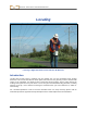
Conducting a Background Noise Check
With the transmitter off, power up the SE receiver and walk the bore path while monitoring the signal
strength on the receiver’s screen, noting any locations where it changes. A general rule is that the
background noise should be at least 150 points less than the transmitter’s signal strength when measured
at the maximum depth for that bore. In the figure below, the red flag area denotes an increase in
background noise.
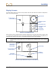
One-Person Background Signal Strength Check (No Transmitter)
Intended Bore Path
Background Noise