LevelOne FCS-4000 / FCS-4100 / FCS-4200 FCS-4300 / FCS-4400 / FCS-4500 Day/Night P/T/Z IP Speed Dome Camera User Manual Ver:2.1.0-0804 Copyright (c) 2008 Digital Data Communications Co., Ltd. All Rights Reserved.
Before You Use This Product The use of surveillance devices may be prohibited by law in your country. The Network Camera is not only a high-performance web-ready camera but also can be part of a flexible surveillance system. It is the user’s responsibility to ensure that the operation of such devices is legal before installing this unit for its intended use. It is important to first verify that all contents received are complete according to the list in the "Package Contents" chapter.
ATTENTION 1. 2. 3. 4. 5. 6. 7. 8. All operation please refer to the instruction. Please don’t place the product on unstable desk or bracket. Please avoid any liquid permeate inside of the machine in case damage the product. Before wiring, please follow all electronic safety standards, and using the original attached power supply adapter. The RS-485 and Video signal of the product use TVS grade lightning protection technology can prevent effectively lightning strike under 500W.
Table of Contents Before You Use This Product....................................................................................... 2 Package Contents ....................................................................................................... 2 Functions and Operation directory............................................................................... 2 Hardware Installation ...................................................................................................
Package Contents FCS-4000/FCS-4100/FCS-4200/FCS-4300/FCS-4400/FCS-4500 Power Adapter Power & A/V Cable LAN Cable Alarm Cable CD Manual/Utility Quick Installation Guide Functions and Operation directory Followed is the brief introduction of main functions and operations of LEVELONE IP SPEED DOME, different operation platform may have different operating methods, generally base on the manual. Special operating demand, please contact your dealers.
Focusing control: Users can press the zoom button to adjust the image viewing distance. Iris control The factory default is auto iris, ensuring to have the best image quality. In particular circumstances, the operator can also use manual iris feature.
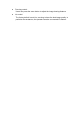
Hardware Installation Installation Notice Please be sure to follow all the steps of the instructions. Wrong installation may damage the product. FCS-4300/4400/4500Housing installation Outer housing fixing as below, click down the iron slice then pull it up. Before install inner housing, please hook the safety lock of outer housing on the fixing socket of inner housing, in case of installation accidents. Please fix the three screws on the side before install the camera.
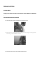
Finally cover up the smoked cover to accomplish the installation. Please be sure hands are clean while cover up, or it may dirty the cover. It’s recommended to tear off the protect membrane after installation is finished, or wear on gloves. FCS-4000/4100/4200Housing installation The installed spot must be held to the product firmly, in case the image shaken while the camera operates. Put the cable tube into the power box, and screw it. Using hexagon screw driver to fix the housing and bracket.
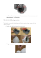
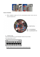
unscrew the bottom screw to install cables. Power&A/V Cable Alarm Cable Microphone Cable LAN Cable Speaker Cable Reset Button Insert the plug, and pull these cables through out from the bottom of bracket. For the alarm cable Brown Red Orange Yellow Green Blue Black White DI 1 DI 2 DI 3 DI 4 GND NC COM NO Hook up the safety buckle, and screw the two screws to fix the power box.
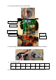
Camera installation Before installation, please set for the communication protocol, baud rate and camera ID address first. ID address setup There are 8 dip-switchers on the PCB board. Please set it up as below: All the dip-switchers are OFF. *Remarks: Please reboot the camera after the camera setup is done.
Protocol setup The dip-switchers are for protocol setup. Please set it up as below: No.5 is ON. *Remarks: Please reboot the camera after the protocol setup is done. Alarm Dip-switchers The dip-switchers are for DI/DO setup. Please set it up as below: NO. 5/6/7/8 is ON. Aim the camera plug to the bottom socket to connecting.
You can also follow the triangle in front of camera and aim at the bottom screw to fixing. After the camera is installed, please turn the camera and fixing the two side screws. Finally cover up the smoked cover to accomplish the installation. Please be sure hands are clean while cover up, or it may dirty the cover. It’s recommended to tear off the protect membrane after installation is finished, or wear on gloves. Bracket installation CAS-4000A wall mount Kit Fixing power box on the wall.
Hook up the safety buckle, and screw the two screws to fix the power box. CAS-4000B ceiling mount kit Fixed the iron tube to the cover of power box. CAS-4000C corner mount kit Combine two brackets, and use the spanner to fix the screw. Turn the screw to tighten the brackets and power box.
The assembly completed. CAS-4000D pole mount kit Fixed the bracket on the rear of power box. The assembly will be done after the stainless ring is hooped.
Software Installation In this manual, "User" refers to whoever has access to the Network Camera, and "Administrator" refers to the person who can configure the Network Camera and grant user access to the camera. At the end of the hardware installation, the Administrator must place the product software CD into the CD-ROM drive of the PC running in MS Windows. An auto-run program will pop up (If the program is not on auto-run, go to the root directory of the software CD and click on “autorun.exe”).
Upon IP CamLocator’s start up, this program searches for LevelOne’s products on the same LAN. After searching, LevelOne Video Servers or Network cameras will be located by the IP CamLocator. There may be several entries shown in the window. The Administrator may differentiate the Network cameras with the model number and MAC address. The IP addresses shown in the "IP Address" field reflect those on the local network. They may be from the DHCP server.
complete installation. Custom Setup Type: You may install the system to the directory of your preference and choose which feature(s) you want to install to the PC. Hint: You may, for instance, install only Playback and/or LiveView on the PC at home or other remote site from which you do not install the camera but are going to watch them remotely.
How to Use IP CamLocator This chapter introduces how to monitor the image from the camera using IP CamLocator. The LevelOne video server and Network camera can be used with Microsoft web browsers and IP CamLocator in Windows operation systems. This document focuses on introducing IP CamLocator. Initial use IP Cam Locator Click Start -> Program Files -> LevelOne -> IP Cam Locator -> IP Cam Locator.
Main Menu Camera Click this button to get into common information of all Network cameras in network. You can connect the specific Network cameras to get life video and to optimize video setting. User Click this button to get into user basic setting information of all Network cameras in network. You can connect the specific Network cameras to get and set basic values. This section includes Info, User, Date Time, TCP/IP, PPPoE and DDNS. Note: Only the administrator has access to the Settings.
seeking from 192.168.0.2, to 192.168.0.254. If any of the address inside this range is free, the Network Video server will be assigned to this IP address, and its subnet mask would be 255.255.255.0. Link to IE:After searching Network Cameras in network, you can click to specific Network Cameras in search area and press Link to IE to use IP cameras with Microsoft web browses. Setup Choose a network camera, click on Setup to change the configurations.
Account settings: The account setting is displayed. You can change the account setting here. Press “Next” to continue, “Previous” to go back, “Cancel” to go to the main page.
Date/Time settings: You can set the date/time of the network camera here. See ”Hint” for details. Press “Next” to continue, “Previous” to go back, “Cancel” to go to the main page.
Network settings: You can change the network settings of the network camera here. See “Hint” for details. Press “Next” to continue, “Previous” to go back, “Cancel” to go to the main page.
PPPoE settings: You can change the PPPoE settings here. See “Hint” for details. Press “Next” to continue, “Previous” to go back, “Cancel” to go to the main page.
DDNS settings: You can change the DDNS settings here. Press “Next” to continue, “Previous” to go back, “Cancel” to go to the main page.
Apply settings: Click on “Apply” to use the new settings. Choose “Reboot system to apply new (network) settings” to reboot after the settings are applied.
Upgrade Choose a network camera, click on Upgrade to upgrade the firmware. You have to key in the username and password of the administrator to enter the upgrade page. The following screen will display: Choose the firmware image file you want to upgrade and press “Upgrade” to start. The device will automatically reboot after upgrade.
Factory Default Choose a network camera, click on Factory default to reset the configurations to default. You have to key in the user name and password to use the factory default function. Click on “OK” to continue. The device will automatically reboot after the configurations set to default.
Reboot Choose a network camera, click on Reboot in the user name and password to use the reboot function. Click on “OK” to continue. The device will automatically reboot. to reboot the device.
User The System page provides you all Network Cameras configurations in the network with product or downloaded configuration file information, including Info, User, Date Time, TCP/IP, PPPoE and DDNS. Load configuration File:Select From PC File or From Device, the former can load information of downloaded configuration file and the latter can load Network Camera configurations in the network.
From PC File:Click it and press Load to select configuration location from PC. Note: • Configuration file format is *.conf.
From Device:Click it and press Load to select the specific device in the network. Type the Username and Password to load configuration from device. Note: If you have connected to the specific device before, you don’t have to type the Username and Password again.
After loading, you can get configuration from PC files or devices. IP CamLocator displays the sub folders including Info, User, Date Time, TCP/IP, PPPoE and DDNS. Info The Info page provides you with product factory information, including Product Name, Firmware Version and Web version.
User The Network Camera default account and password setting is “root/MAC address of IP camera (in capital letters)”. IP CamLocator provides to assign a password if the Network Camera is intended to be accessed by others. Use this menu to set the username and password of Administrator and up to 9 different users (User 1 to User 9), and the authentication access right of each group. Username:Set a user name between 5 and 16 characters. Password:Set a password between 5 and 16 characters.
Date/Time Current date & time:This displays the current date and time of the camera. PC clock:This displays the date and time of the monitoring PC clock. Adjust:Select one of four time adjusting modes. Keep current setting:Select this mode to keep the current date and time of the camera. Synchronize with PC:Select this mode to make the date and time of the camera the same as the monitoring PC. Manual setting:Select this mode to manually adjust the date & time of the camera.
TCP/IP HTTP Port:Select port 80 in general situations. If you want to use a port number other than 80, select the text box and enter a port number between 1024 and 65535. Note: • When you have set the HTTP port number to a number other than 80 on the Network setting page or in the Setup Program, access the camera by typing the IP address of the camera on the web browser as follows: Example: when HTTP port number is set to 2000 Æ http://192.168.0.100:2000/ MAC Address:Display the MAC address of the camera.
Secondary DNS:Enter the IP address of the secondary DNS server, if necessary.
PPPoE Use this when you connect the camera through PPPoE (Point -to- Point Protocol over Ethernet). PPPoE connection is the protocol that is widely used in xDSL (digital affiliate line such as ADSL, VDSL or SDSL) as the authentication and connection system. IP Address:The IP address obtained at the PPPoE connecting with network. User ID:Enter the user ID for authentication necessary for PPPoE connections. Type it up to 64 characters.
DDNS Server Name:Select the DDNS Server User ID:Enter the user ID for authentication necessary for DDNS connections. Type it up to 64 characters. Password:Enter the password for authentication necessary for DDNS connections. Type it up to 32 characters. Confirm:Re-type the password to confirm. Hostname:Enter the host name that is registered to the DDNS server. Note: • When you want to use DDNS function, you need to register an account in DDNS server first.
About This page displays IP CamLocator information including Version, Copyright and Product Date information Note: • This computer procedure is protected of the right law and international convention. Making all or part which spread a procedure again without permission, may cause serious civil and criminal sanction and mention most severe telling in accordance with the law.
How to Access to the Network Camera This chapter introduces how to monitor the image from the camera using Microsoft web browser. The LevelOne video server and Network camera can be used with Microsoft web browsers and IP CamLocator in Windows operation systems. This section focuses on introducing camera web server. The recommended browser for Windows is Internet Explorer 6.0 or above. The functions of the camera should be set by the Administrator.
Configuration of Main Console Language You can click the pulldown box to select system language, including English, Traditional Chinese, German, Danish, Greek and Korean. Setting This function is only for the Administrator. Click this button to get into the Basic and Advance settings menu. Client Setting Mode: Click the pulldown box to choose between MPEG4 and MJPEG video compression mode. Note:MJPEG streaming is unavailable if RTSP mode is ON.
Video Buffer: Turn the Video Buffer function On/Off. The Video Buffer function makes the streaming more smoothly in unsteady network environment, but might cause a little delay in live viewing. Image Setup You can use the tool bar to optimize video brightness, contrast, and saturation.
Pan / Tilt control Click the arrow button of the direction you want the IP camera to move. Note: This function is only for PTZ Cameras. You can also Pan/Tilt cameras by left-clicking the main screen Move the camera toward the preset direction. Before you start this function, you need to specify Guard tour settings in the Setting Menu under Advance / Patrol setting. Adjust camera focus. You can use the tool bar to optimize video brightness, contrast, and saturation.
Live View Snapshot: You can capture a still image shot by the camera and save it in your computer. Press , and a snapshot window will appear. Click “Save” to save the picture in your computer. Click “Close” to return to the view page. Digital Zoom in / out the image via the monitor window Click to display the digital zoom in window. Pull the to adjust the digital zoom range, and it will be showed on the above window. You can use the left click of your mouse to move the to any where on the window.
camera(s) via the Ethernet using your microphone. Video play buttons: :Pause the current video :Play the video. :Stop the current video. :Record the current video.
Basic Setting Click the “Basic” folder to display the sub folders, including System, Camera, Network, and Account. System Information The Information page provides you with product factory information, including Product name, Firmware version, and Web version.
Day & Time Current date & time:This displays the current date and time of the device. PC clock:This displays the date and time of the monitoring PC clock. Date & time format:Click the pulldown box to select among different time display formats, including yyyy-mm-dd hh:mm:ss (year-month-day hour:minute:second), mm-dd-yyyy hh:mm:ss (month-day-year hour:minute:second), and dd-mm-yyyy hh:mm:ss (day-month-year hour:minute:second). Adjust:Select one of four time adjusting modes.
Reboot:Click this button to reboot the device. A confirmation dialogue will appear. Click OK to proceed. It takes about two minutes to reboot the device. Factory default:Click this button to reset the device to the factory default settings. A confirmation dialogue will appear. Click OK to proceed, the network indicator on the device will start to blink. After completing adjustments to the default settings, the device will reboot automatically. Do not turn off the device until the device reboots.
Camera General RTSP: Switch the RTSP streaming On/Off. Note: • RTSP: Real Time Streaming Protocol. RTSP is supported by most of the media clients . (RealPlayer, Media Player, QuickTime, etc…) Deinterlace Filter:Switch the deinterlace filter on/off. Overlay:Select to add Text Overlay or Privacy Mask on/off the display screen. Text Overlay:Enables users to see some information on the display screen, including Date/Time and user-defined text. You can also change the background color.
MPEG4 Computer View MPEG4 viewer port (If RTSP mode is OFF) Unicast streaming Video/Audio port number : Specify the transmission port number of the video data. It is initially set to 8090. Specify an even number from 1024 to 65534. Image Size:Specify the image size the network camera transmits. You can choose among 704 × 480, 352 × 240 and 176 × 120 for NTSC mode and 704 × 576, 352 × 288 and 176 × 144 for PAL mode. Frame rate:Set the frame rate of the MPEG4 image.
RTSP (If RTSP mode is ON) RTSP port: Specify the transmission port number of RTSP streaming video. Default value is 554. Viewer authentication: If the viewer authentication is ON, users viewing through RTSP will be requested to key-in username and password. RTP (If RTSP mode is ON) Unicast streaming: Unicast streaming Video/Audio port range: Specify the transmission port range of RTP streaming video. RTP will select a port randomly from the range.
unit “fps” stands for “frames sent per second”. Quality Auto:The quality and bitrate will be automatically decided according to the frame rate. Fixed Quality:The selectable values are Medium, Standard, Good, Detailed and Excellent. Fixed Bitrate:Set the bit rate of MPEG4 image transmission for a line. Selectable values are 64, 128, 256, 384, 512, 768, 1024, 1280, 1536 and 2048 kbps. Note: • The selected frame rate and bit rate are a tentative value.
11000. Specify an even number from 1024 to 65534. Time-To-Live: Set the maximum TTL that multicast can pass through. Image Size: The Image size of Mobile view is fixed at 176x120. Frame rate:Set the frame rate of the MPEG4 image. Selectable values are 5, 10, 15, 20 fps. The unit “fps” stands for “frames sent per second”. Quality Fixed Bitrate:Set the bit rate of MPEG4 image transmission for a line. Selectable values are 64, 32, and 16kbps..
MJPEG Note: • MJPEG settings are unavailable if the RTSP mode is ON, which means the MJPEG streaming is closed. MJPEG viewer port Unicast streaming Video/Audio port number : Specify the transmission port number of the video data. It is initially set to 8070. Specify an even number from 1024 to 65534. Note: • Unicast streaming:Specify the transmission port number of the video data and audio data used when UDP (Unicast) is selected with the TCP/UDP transmission switching icon in the main viewer.
Network Information MAC address:Display the MAC address of the device. Obtain an IP address automatically (DHCP):If a DHCP server is installed on the network, to select this while the IP address is assigned by the DHCP server. Note: • When you set Obtain an IP address automatically (DHCP), make sure that the DHCP server is working on the network. Use the following IP address:Select this when a fixed IP address is set. IP address:Enter the IP address of the device. Subnet mask:Enter the subnet mask.
follows: Example: when HTTP port number is set to 2000 Æ http://192.168.1.
PPPoE Use this when you connect the device through PPPoE (Point -to- Point Protocol over Ethernet). PPPoE connection is the protocol that is widely used in xDSL (digital affiliate line such as ADSL, VDSL or SDSL) as the authentication and connection system. IP address:The IP address obtained at the PPPoE connecting with network. User ID:Enter the user ID for authentication necessary for PPPoE connections. Type it up to 64 characters.
DDNS Server name:Choose the DDNS Server from the list. User ID:Enter the user ID for authentication necessary for DDNS connections. Type it up to 64 characters. Password:Enter the password for authentication necessary for DDNS connections. Type it up to 32 characters. Re-type password:Re-type the password to confirm. Host name:Enter the host name that is registered to the DDNS server. Note: • When you want to use DDNS function, you need to register an account in DDNS server first.
UPnP The device includes support for UPnP, which is enabled by default. If also enabled on your computer, the device will automatically be detected and a new icon will be added to “My Network Places.” It provides port forwarding for opening a port in a router or firewall in a private network in order to let a party from the outside world contact a user inside. HTTP port:Enter the HTTP port number and default HTTP port is 80. SSL port: Enter the SSL port number and default SSL port is 443.
IP Notification When network notify type is set to On, you can send an e-mail notification of the completion of the network setting. Notify type:Select type of DHCP, Static IP and PPPoE will notify. SMTP server name:Type the SMTP server name up to 64 characters, or the IP address of the SMTP server. Authentication:Select the authentication required when you send an email. Off: Select if no authentication is necessary when an email is sent.
Type the text of the E-mail up to 384 characters. Default value provides network information including IP, Port, MAC, Model, Firmware Version and Web Version.
Security Account The device default account and password setting is “root/MAC address of IP camera (in capital letters)”. That means everyone might access the device including the configuration as long as the IP address is known. It is necessary to assign a password if the device is intended to be accessed by others. Use this menu to set the user names and passwords of Administrator and up to 9 different users (User 1 to User 9), and the access right of each user.
HTTPS HTTPS is a URI scheme used to indicate a secure HTTP connection. It is syntactically identical to the http:// scheme normally used for accessing resources using HTTP. Using an https: URL indicates that HTTP is to be used, but with a different default TCP port (443) and an additional encryption/authentication layer between the HTTP and TCP. You can use the IP camera through HTTPS easily by using https:// instead of http://. Create & Install: Create a self-signed certificate for HTTPS to recognize.
Advance PTZ Control In this section, it provides Pan, Tilt, Zoom, Focus, Iris and Auto Pan speed control setting saved, as well as the Protocol, Baud rate and Address which depend on Speed Dome control module. Setting Pan speed:Use it to move bar from 0 to 100. Tilt speed:Use it to move bar from 0 to 100. Zoom speed:Use it to move bar from 0 to 100. Focus speed:Use it to move bar from 0 to 100. Iris speed:Use it to move bar from 0 to 100. Auto Pan speed:Use it to move bar from 0 to 100.
Preset Position In this section, up to 32 Pan / Tilt and Zoom positions can be saved, as well as the home position, which the camera faces to when the power is turned on. Setting Set:Use it to save the camera position to a preset number. Carry out the following steps. 1. Move the camera to the position to be saved while you are checking the image with the main console. 2. Write the preset position name in Preset Pos. Name text box. 3. Click the SET. The camera position is saved. 4.
preset position setting.
Patrol There are four patrol tours to set for composing different preset positions. Each one lists up to 8 positions which can be programmed, and the camera moves to the programmed positions sequentially. The camera stops when it moves to the last preset position. General Tour name:Rename the tour name. Tour position Order:There are 8 orders to select for camera directions. Select Pos.:There are up to 32 preset positions to choose for each order.
3. Click the SET. The tour position is saved. 4. Follow the steps to set the other orders. 5. Click the OK to save the tour.
FTP Client Use this menu to set up for capturing and sending images to an FTP server. By using FTP client function, you can send the image and audio file which has been shot and recorded linked with the external sensor input or with the built-in motion detection function to FTP server. FTP client setting menu is composed of two tabs, General, Alarm sending and Periodical sending. General FTP client function:To activate the FTP client function, select On. The FTP client setting page appears.
Set to forward the image and audio file to the specified FTP server linked with the alarm detection by the external sensor input or by the built-in motion detection function. Select On to send the image and audio file to FTP server linked with the alarm detection. Remote path:Type the path to the destination in FTP server up to 64 characters. Image file name:Type the file name you want to assign to the images when sending to the FTP server.
Periodical sending You can set to send an image file to FTP server periodically by selecting On to send the image file to FTP server linked with setting period. Remote path:Type the remote path up to 64 characters. Image file name:Type the file name of the image sent to FTP server up to 10 alphanumeric characters, (hyphen) and _ (under score). Suffix:Select a suffix to be added to the file name sent to FTP server. None:The name of the sent file will be the Image file name.
SMTP Set the SMTP menu when you want to send an image via e-mail. By using Mail (SMTP) function, you can send a mail with attached image which has been shot linked with the external sensor input or with the built-in motion detection function. The image file can also be sent periodically. E-Mail (SMTP) setting menu is composed of three tabs, General, Alarm sending and Periodical sending. General Select On when you use the SMTP function. The common setting options are displayed below.
followings. SMTP: Select if SMTP authentication is necessary when an e-mail is sent. POP before SMTP: Select if POP before SMTP authentication is necessary when an e-mail is sent. Note: • When you set to On, be sure to select either or both SMTP or/and POP before SMTP. POP server name:It is necessary when the POP before SMTP is selected in Authentication. Type the POP (receiving mail) server name up to 64 characters, or type the IP address of the POP server.
Alarm sending Set to send the mail with connection to the alarm detection by the external sensor input or by the built-in motion detection function. Alarm sending:Select On to set to send mail with connection to the alarm detection. File attachment:Set whether an image file is attached to the mail sent or not. When On is selected, the image file made by the settings below is attached. When Off is selected, only the message is sent.
the Alarm Buffer — Alarm buffer setting Menu on page.
Periodical sending You can set to send an image file by SMTP server periodically by selecting On to send the image file by SMTP server linked with setting period. Image file name:Type the file name of the image sent by SMTP up to 10 alphanumeric characters, (hyphen) and _ (under score). Suffix:Select a suffix to be added to the file name sent by SMTP. None:The name of the sent file will be the Image file name. Date & time:The date & time suffix is added to the Image file name.
sensor input or with the built-in motion detection function to HTTP server. HTTP client setting menu is composed of two tabs, General and Alarm sending. General HTTP event: Set up the HTTP server URL, port, user id, password, and proxy server settings.
Alarm sending Set to send the mail with connection to the alarm detection by the external sensor input or by the built-in motion detection function. Alarm sending:Select On to set to send mail with connection to the alarm detection. Motion Detection:Click it on for using Motion Detection function as a sensor. You can set the motion detection function page. Note: • Motion Detection works only when the Video mode is set to MPEG4 and the Cropping is set to Off.
Schedule When you click Schedule on the Advanced mode menu, the Schedule setting menu appears. This is the same menu as the setting menu which is displayed when you click Schedule to set Effective period and Schedule in FTP client setting menu, e-Mail (SMTP) setting menu, Alarm out setting menu and so on. Example: When setting e-Mail (SMTP) (the alarm sending) in the Schedule setting menu. Setting Schedule selection Select the list box to specify the schedule you want to set.
Alarm Input When you click Alarm Input on the Advance mode menu, the Alarm output setting menu appears. You can set in this menu to control the external alarm input of I/O port on the rear of the camera linked to FTP and SMTP sending function. Note:This function is only for Cameras which support digital input/output. Setting Sensor input 1:Click it on for using external sensor which is connected to sensor input1 of the camera I/O port.
Alarm Buffer You can set the Pre-alarm image and audio (the image and audio before the alarm detection) and the Post - alarm image and audio. These can be set when Alarm sending FTP client setting menu or Image memory setting menu is set to On, and besides when Use alarm buffer is selected. Setting Alarm buffer:To activate the Alarm buffer function, select On. The basic setting options are displayed below. When you do not use the Alarm output function, select Off.
Motion Detection When you click Motion Detection on the Advance mode menu, the Motion Detection setting menu appears. There are three Motion Detection functions as sensors to set for different detecting zones. Each one has Threshold and Sensitivity inputs which you can adjust to specific zone sequentially. Motion Detection function can support to FTP, SMTP and Alarm output for capturing and sending images or starting alarm output.
A detecting zone 1 appears and use mouse to adjust and move the zone boundaries and position. Use tool bar to set Threshold and Sensitivity value. Follow the steps to set the other Motion Detection. Click the OK to save the setting. Note: • Be careful! Motion Detection function don’t work with Patrol function at same time.
System Log The System Log function allows users to review any changes and events happened. The system starts logging automatically after started. Remote Log: Enables user to send the log data to a specified log server.
Trouble shooting sheet Troubles Probable Reasons Wrong power cable connection. The power adapter broken. No action while power on. Fuse broken. No image. Power cable is not in well The indicator isn’t flashing. connection. Solutions Reverse. Change. Change. Reconnected. Start up with factory Firmware is hang up. default setting by pressing the reset button over 5 seconds then releasing it. The camera ID address is Having image but can’t control. The indicator isn’t flashing. incorrect.
Technical Parameters M od e l FCS-4000/4300 FCS-4100/4400 Co mpr ess io n FCS-4200/4500 MJEG/MPEG4 M od e 704x480 pixels(NTSC) Max. 704x576 pixels(PAL) Resolut ion 160x120: 30/25fps 320x240: 30/25fps F ra m e R at e 704x480: 30/25fps 1/4" Exview HAD CCD Sensor L en s Minimu m Illumination 4.0~72mm/F1.4~3.0 3.5~91mm/F1.6~3.8 3.4~122.4mm/F1.6~4.5 0.7Lux/F1.4 1.0Lux/F1.6 0.1Lux/F1.6 1/1~1/10,000 Shutter (sec) A u d io C ode c G.
GNU GENERAL PUBLIC LICENSE Version 2, June 1991 Copyright (C) 1989, 1991 Free Software Foundation, Inc. 59 Temple Place, Suite 330, Boston, MA 02111-1307 USA Everyone is permitted to copy and distribute verbatim copies of this license document, but changing it is not allowed. Preamble The licenses for most software are designed to take away your freedom to share and change it.
Finally, any free program is threatened constantly by software patents. We wish to avoid the danger that redistributors of a free program will individually obtain patent licenses, in effect making the program proprietary. To prevent this, we have made it clear that any patent must be licensed for everyone's free use or not licensed at all. The precise terms and conditions for copying, distribution and modification follow.
c) If the modified program normally reads commands interactively when run, you must cause it, when started running for such interactive use in the most ordinary way, to print or display an announcement including an appropriate copyright notice and a notice that there is no warranty (or else, saying that you provide a warranty) and that users may redistribute the program under these conditions, and telling the user how to view a copy of this License.
compilation and installation of the executable. However, as a special exception, the source code distributed need not include anything that is normally distributed (in either source or binary form) with the major components (compiler, kernel, and so on) of the operating system on which the executable runs, unless that component itself accompanies the executable.
It is not the purpose of this section to induce you to infringe any patents or other property right claims or to contest validity of any such claims; this section has the sole purpose of protecting the integrity of the free software distribution system, which is implemented by public license practices.
NO WARRANTY 11. BECAUSE THE PROGRAM IS LICENSED FREE OF CHARGE, THERE IS NO WARRANTY FOR THE PROGRAM, TO THE EXTENT PERMITTED BY APPLICABLE LAW. EXCEPT WHEN OTHERWISE STATED IN WRITING THE COPYRIGHT HOLDERS AND/OR OTHER PARTIES PROVIDE THE PROGRAM "AS IS" WITHOUT WARRANTY OF ANY KIND, EITHER EXPRESSED OR IMPLIED, INCLUDING, BUT NOT LIMITED TO, THE IMPLIED WARRANTIES OF MERCHANTABILITY AND FITNESS FOR A PARTICULAR PURPOSE. THE ENTIRE RISK AS TO THE QUALITY AND PERFORMANCE OF THE PROGRAM IS WITH YOU.