
User's Manual

11
INSTALLATION
4. Installation
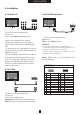
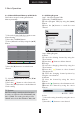
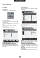
4.2.3) Video1/2
ྙ Connect as the drawing shown.
ྚ Power on.
ྛ Press the [VIDEO1]/[VIDEO2] button.
- When connecting the TV to external
equipment, match the jack colors (Video=
yellow, Audio Left = white, and Audio Right =
red).
- To avoid picture noise (interference), leave an
adequate distance between the External Video
Equipment and TV.
- Use the ISM Method of Panel Function Menu
to avoid having a fixed image remain on the
screen for a long time. Typically a frozen still
picture from a VCR. If the LetterBox picture
format is used, the fixed image may remain
visible on the screen.
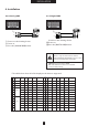
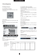
4.2.4) S-VHS
ྙ Connect as the drawing shown.
ྚ Power on.
ྛ Press the [S-VHS] button.
[Caution]
Audio input must be connected with [Video1].
[Note]
S-VHS cable is not included in the product package.
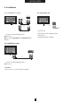
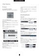
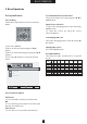
4.2.5) SCART connection
Connect as the drawing shown.
Power on.
Press the [VIDEO2] button.
[Caution]
1. Do not use Scart and video2 port simultaneously.
2. Connected devices will not display properly in case
both Scart and Video 2 ports are connected.
3. Mode switching between Scart-RGB and Scart-
Composite is done automatically.
[Note] SCART cable is not included in the
product package.
S-VHS OUTPUT
VCR
R
L
V
R
L
AUDIO Cable
(MONO)
VIDEO1
S-VHS Cable
S-VHS
SCART I/O
SCART I/O
VCR
SCART Cable
R
L
V
VIDEO2
VIDEO1
R
L
V
Video Cable
Audio Cable
(MONO)
COMPOSITE VIDEO OUT
VCR
YX
X`
X
YYW
YX
YYW
X
X`
At the Video/TV
At the Cable
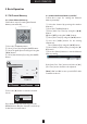
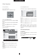
SCART PIN Description
Pin
1
2
3
4
5
6
7
8
9
10
Name
AOR
AIR
AOL
AGND
BGND
AIL
B
SWITCH
G GND
CLKOUT
Description
Audio Out Right
Audio In Right
Audio Out Left + Mono
Audio Ground
RGB Ble Ground
Audio Left + Mono
RGB Blue In
Audio/RGB Switch/16:9
RGB Green Ground
Pin
11
12
13
14
15
16
17
18
19
20
Name
G
DATA
R GND
DATAGND
R
BLNK
VGND
BLNKGND
VOUT
VIN
Description
RGB Green In
RGB Red Ground
Data Ground
RGB Red In
Composite Video Ground
Blanking Signal Ground
Composite Video Out
Composite Video In
21 SHIELD Ground/shield(Chassis)