
Service manual


Service Manual 8-45
FRU Disassembly/Assembly 8
Font module
1. Power down the printer. Leave the power cord plugged in to provide a
ground path for static discharges. Remove the interface cables.
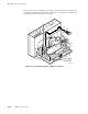
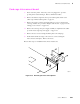
2. Remove the I/O board and the image processor board as explained in the
previous procedures “I/O board” on page 8-42 and “Image processor board”
on page 8-43.
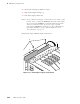
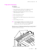
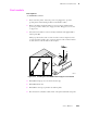
3. Insert the font module in connector J14 (a), and tilt the card upright until it
locks in place (b).
When properly inserted, a tab on each end of the connector slips into a hole
on each end of the module. Also, a pawl on each end of the connector latches
around each end of the module to lock it in place.
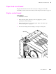
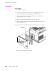
4. Reinstall the image processor board in the card cage.
5. Reinstall the I/O board.
6. Reinstall the card cage top and the rear cabinet panels.
7. Reconnect the host interface cables. Turn on the printer and make a test print.
Tools required
n #1 POSIDRIV® screwdriver
Figure 8-40 Installing the font SIMM on the image processor board
8699-75
J14
J6
J1
J2
a
b
ab
Font
SIMM
module