
Service manual

Service Manual C-1
Appendix
C
Wiring Diagrams
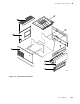
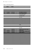
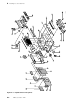
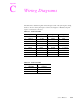
The tables below detail the signals carried through several of the print engine's wiring
harness connectors at the print engine control board. Figure C-1 illustrates the print
engine's control board connectors.
Table C-1. Connector CN2
Pin Signal Pin Signal Pin Signal Pin Signal
1 CVOPN1-0 10 PSS-0 19 FA2-0 28 +5 VDC
2 PEJCT-0 11 +5 VDC 20 FAN2-0 29 GND
3 CVOPN2-0 12 GND 21 FB2-0 30 RTYP2
4 DRMT-0 13 PS1-0 22 FBN2-0 31 no connect
5 PE-0 14 PS2-0 23 GND 32 no connect
6 PIN-O 15 PS3-0 24 PCLMP 33 no connect
7 P-GND 16 PPASS2 25 +5 VDC 34 no connect
8 24S 17 FCOM 26 DRMHP
9 PFS-0 18 FCOM 27 GND
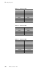
Table C-2. Connector CN3
Pin Signal Pin Signal
1 DRMCOM 4 DRMAN-0
2 DRMCOM 5 DRMB-0
3 DRMA-0 6 DRMBN-0