
Technical data
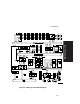


Block Diagram
A-4
CPU/Memory Connector
The CPU/Memory connector is a 242-pin connector for the CPU/Memory board to
provide address/data and control line access to the Primary PCI bus. Through this
connector, the CPU also has access to the Input/Output Advanced Programmable
Interrupt Controllers on the APIC bus. In addition, the I
2
C bus interfaces the CPU to
the 8031 system management subsystem, which monitors fan failures, voltages, and
temperatures.
PCI ISA IDE Xcelerator (PIIX4)
The PCI ISA IDE Xcelerator serves as the bridge from the Primary PCI bus to the
ISA bus. Control and data/address lines from the Primary PCI bus convert to control,
data, and address lines on the ISA bus and vice versa.
The PIIX4 provides a Fast IDE interface for IDE devices, such as the CD-ROM. This
chip also provides the PCI/ISA master/slave interface. It has an 8 X 32 bit buffer for
bus master IDE PCI burst transfers at rates up to 22 Mbytes per second. It contains
two 8237 DMA controllers for fast type F DMA and compatible DMA transfers.
The PIIX4 is also the controller for the Universal Serial Bus (USB). It is a host/sub
controller that moves data between the main system memory and devices on the
serial bus.
It also provides a system timer/counter, programmable clock, refresh request,
interrupt controller, X-bus peripheral support, PCI system error reporting, and system
power management for hardware and software events.
BIOS ROM
The BIOS ROM stores the system BIOS in 512KB of flash memory. The flash
memory allows the BIOS to be upgraded from a diskette or a CD-ROM, such as
Quick Launch.