
Specifications
6–11
Replacement Procedures and Parts
Gas Shock (107961–005)
1. Unplug the printer power cord from the AC receptacle to insure that
there are no hazardous voltages present while servicing this equipment. It
is also recommended that an anti–static wrist strap (29–26246–01) be
worn, especially while servicing logic components.
2. Remove the paper supply from the print station and tractors. Remove the
paper chains, paper tent, and wire paper guide.
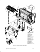
3. As shown in Figure 6–17 (page 6–60, item #2), remove the inner access
panel by removing seven (7) 5/16” screws.
WARNING
The printer cover is very heavy and personal injury, or equipment
damage can result if care is not exercised while replacing the gas shock.
4. Raise the cover to its full height, if the cover will not easily remain in
this position, another person should be asked to assist.
5. With the cover in this position extract the locking clip located on the top
swivel socket of the gas shock. Once this clip is extracted, the socket can
be pulled from the ball. The top cover can now be rotated backward. The
cover hinges will support its weight, but it is recommended that another
means of support is used.
6. From inside the bottom cabinet immediately above the power supply,
extract the locking clip located on the bottom swivel socket of the gas
shock. The gas shock can now be removed from the printer.
7. Reverse the removal steps to replace the new gas shock.