
User guide

MR-1000 user guide V1.3
5
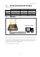
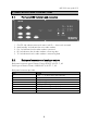
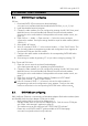
2.1. Front panel LED indicators and connectors
1. On/Off –led indicates auto switch status. Led On = Auto switch activated
2. Main/standby –led indicates the active radio modem.
3. Pwr –led indicates that the radio modem is powered
4. RX –led indicates that the radio modem is receiving data
5. TX –led indicates that the radio modem is transmitting data
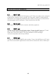
2.2. Back panel connector and analogue outputs
Back panel connector type is Phoenix Contact DFK-PC 4/8-GF- 7, 62.
Socket type is Phoenix Contact 1828304 PC 4/ 8-STF- 7, 62.
Back panel connector pin order
PIN
NAME
1
+36 … +75 VDC Input (48V nominal)
2
GND
3
Pwr1 sense, option
4
Pwr2 sense, option
5
FAN1 speed analogue output, option
6
FAN2 speed analogue output, option
7
N/A
8
N/A
2. INDICATORS AND CONNECTORS