
User manual

Blackfin DEV-BF548-Lite. DEV-BF548DA-lite Hardware User Manual
14
4 Connector Description
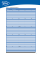
4.1 X4 –RJ45 Ethernet Connector
Pin No. Signal (Core Module) IO-Type
1
T
X+ O
2
T
X- O
3 RX+ I
4 NC -
5 NC -
6 RX- I
7 NC -
8 NC -
Table 4-1: Ethernet Connector
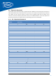
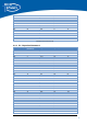
4.2 X9 –SD-Card Connector (bottom Mount)
Pin No. Signal (Core Module) Description (SD Card)
0 SD_D2 DAT2
1 SD_D3 CD/DA
T
3
2 SD_CMD CMD
3 GND VSS1
4 3,3V VDD
5 SD_CL
K
CL
K
6 GND VSS2
7 SD_D0 DAT0
8 SD_D1 DAT1
9 - CD
10 - WP
Table 4-2: SD-Card Connector
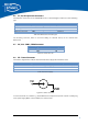
4.3 X6 – JTAG Bypass Connector
The JTAG connector is compliant with any Blackfin JTAG Emulator from Analog Devices. When an
external JTAG emulator is attached the on-board JTAG is bypassed and the external one is automatically
used.
4.4 X11 – USB-UART Connectors
Connects either UART0 (when S3 is in Pos 1) or UART1 (when S3 is in Pos 0) to the USB Interface
enabling a COM Port on the PC. UART0 is standard console IO for the BLACKSheep Software.
4.5 X12 UART Expansion Pads
When S3 is in position 1 the UART1 on PortH (TX, RX) is available on the expansion pins and
disconnected from the USB-UART Chip.
Pin No. Signal Signal Type
1
T
xD Blackfin Input Core Module
2 RxD Blackfin Output Core Module
3 GND
4 3V3 Regulated Power
Table 4-3: UART1 additional Header