Configuration Guide of H.264 IP Cameras & Video Server Note This manual provides information to configure IP Camera and Video Server products through admin page settings. For the connection to the admin page enter http://[IP_address:http_port]/admin.htm into the address field of internet explorer.
Configuration Guide of H.264 IP camera and Video Server Products Revision History Date 2011-10-11 Rev No 1.5 ⓒ 2011 Speco Technologies Description Creation of this Document Rev.1.
Configuration Guide of H.264 IP camera and Video Server Products Indications: Warning : Death or Serious Injury will occur without complying with Warning. Caution : Operational Problem(Faulty & Malfunction) will occur without complying with Caution. Note : Technical information for User‟s Usage. ⓒ 2011 Speco Technologies Rev.1.
Configuration Guide of H.264 IP camera and Video Server Products Contents Contents................................................................................. 4 1. Preparation for the connection................................................ 5 1.1. Product Installation ................................................................................. 5 1.2 PC Requirements ..................................................................................... 7 2. Admin Tool ............................
Configuration Guide of H.264 IP camera and Video Server Products 1. Preparation for the connection 1.1. Product Installation Brief information for rapid installation is provided in this section. For more detailed information, you are recommended to refer to pertinent documentations provided with the product. 1. Apply Power to the device and connect with Network. AC adapter which is compliant to the specification for products should be used. Misuse of power supply can cause damage to products.
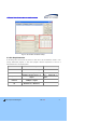
Configuration Guide of H.264 IP camera and Video Server Products Fig 1-1. IP installer Network Configuration Setup C. Assign network parameters needed for connection to the product. Please follow through the following procedures. a. Double click on a product you want to set up. b. The selected product will be highlighted and network parameter settings will be shown. Each product can be identified with unique MAC address. Refer to the following figure for an example. c.
Configuration Guide of H.264 IP camera and Video Server Products Fig 1-2. IP installer Parameter Setup 1.2 PC Requirements AV streaming data received from IP camera or video server can be decoded or stored in a PC running SPECO-NVR program or other CMS program. Minimum requirement of the PC is recommended as in the following table.
Configuration Guide of H.264 IP camera and Video Server Products 2. Admin Tool The operational condition of the IP cameras and video servers can be set up over the network. This chapter describes general information of setting up these products over the network. The products covered include H.264 IP Cameras and Video Server products. 2.1. Access Access to Admin Tool is available using Internet Explorer and exclusive “Speco-NVR”. 1.
Configuration Guide of H.264 IP camera and Video Server Products Fig 2-1. Access to Admin Page using Speco-NVR 3. Input User Name and Password. Accessing to Admin Page is required to insert User Name and Password. Factory default “User Name” and “Password” are set as “admin” and “1234”, respectively. Click on “OK” button to enter into the Basic Setup page of Admin mode. If you have changed the username and password of the Administrator, you must log on with the changed username and password.
Configuration Guide of H.264 IP camera and Video Server Products For secured security, it is recommended to change the User Name and Password during the installation. For the details, refer to the [User Admin & Time Setup]. Once User Name and Password are forgotten, it is required to restore the Factory Default Value as “admin” and “root” by pressing the Factory Default Button for about 5 sec while power is applied. All Setting parameters will be restored with Factory Default Values.
Configuration Guide of H.264 IP camera and Video Server Products 2.2. Layout of Admin Page Upon initiation of the admin page, the screen similar to the following picture will be shown. The left side of the admin page shows various admin page menus, while the right side shows the settings of selected admin menu. Click each of the menu items at the left to go into specific admin page. Fig 2-2. Layout of Admin Page Once click on “Live” button, it will close Setting Page and switch to Web Viewing Mode.
Configuration Guide of H.264 IP camera and Video Server Products 2.3. Basic Setup Setup the basic parameters for the operation of the product. Fig 2-3. Basic Setup Class Description Logical name of the product. It is same as the one set-up by IP- System Name installer. You can reassign the logical name. The system name will be shown in the connection through Speco-NVR.
Configuration Guide of H.264 IP camera and Video Server Products Select the type of input audio. Audio Input Selection Select Line In to use Line-out from audio device. Select Mic to use microphone. Maximum four different video profiles can be transmitted through Profile different way. E-Mail Profile is used only for transmitting E-Mail on every event trigger. Max Upload Rate Video Encoding Type Resolution Frame Rate Assign maximum bandwidth of the uplink for the network connected to device.
Configuration Guide of H.264 IP camera and Video Server Products 2.4. Network Setup Setup the network parameters appropriately in accordance with your network environment. Many of the parameters in this page are same as those set up by “IP-Installer”. Fig 2-4.
Configuration Guide of H.264 IP camera and Video Server Products Setup network type, and input the IP address, Subnet Mask, Gateway, DNS1 and DNS2. Ask your network administrator or ISP for the information. DNS2 is used when DNS1 does not work. When the network environment is PPPoE and IP address is assigned PPPoE Setup automatically, select „PPPoE‟ in the network type. Next, fill in the „User Name‟ and „Password‟ fields with the values given by your ISP.
Configuration Guide of H.264 IP camera and Video Server Products address. Input the hostname for the service. Result shows message from Speco DDNS server. Save You must click “Save” button to save all configured parameters. 2.5. 802.1x Setup This is setup page for IEEE802.1x authentication. Fig 2-5. 802.1x Setup Class Description Activation Certificate CA Certificate Client Certificate Private Key ⓒ 2011 Speco Technologies Check at the box to enable 802.1x authentication.
Configuration Guide of H.264 IP camera and Video Server Products Select EAP type and configure Sub Fields Select EAP type to choose authentication method. In order for authentication to be successful, the client and the server must use the same authentication method. Fields used by each method are below.
Configuration Guide of H.264 IP camera and Video Server Products 2.6. Video Setup You can adjust the parameters of input video. For example, the figure below is Video Setup a nd Camera Module Adjust of H.264 MegaPixel camera series. The parameters will vary followi ng the selection of camera modules. Refer to the tables below for the details. Fig 2-6. Video Setup Page Class Applicable Description Select Channel Selection the channel to Model adjust the video parameters.
Configuration Guide of H.264 IP camera and Video Server Products Save Restore original values Camera Module Adjust Save the parameters All Click on “CONFIRM” to restore the default settings. Click on “GO” to adjust the camera module. All All Fig 2-6-1. Camera Module Setup Class Applicable Description Model When the camera is acquiring video from object under bright backlight, it is hard to Module BLC Control Adjust identify the details of target object since the object appears very dark.
Configuration Guide of H.264 IP camera and Video Server Products voltage. It will be activated only with supported product. When the camera is acquiring video from object under bright backlight, it is hard to BLC Control identify the details of target object since the object appears very dark. Apply backlight MP compensation mode for this case. Default mode is backlight compensation Off. DSS (Digital Slow Shutter) Control WhiteBalance Sharpness Activate or Deactivate the use of DSS.
Configuration Guide of H.264 IP camera and Video Server Products 2.7. User Admin & Time Setup You can change the ID and Password of users and also assign different attributes to each user. You must click the “Save” to save all configured parameters. Fig 2-7. User Admin & Time Setup Class Description Administrator User Management Username Administrator Administrator Admin password : “1234”. Administrator ⓒ 2011 Speco Technologies Admin ID. Default ID is “admin” password.
Configuration Guide of H.264 IP camera and Video Server Products Confirm password. Password User Name Password Enter the user ID you want to add. Up to 100 users can be registered in the product. Enter the user password. You can assign different privileges to users in the access to system resources. User Addition Attributes Attribute are Audio, Bi-directional Audio and Pan/Tilt control. For example, if you want a specified user to hear the audio from the device, check Audio in the check box.
Configuration Guide of H.264 IP camera and Video Server Products Time Set Manually Save Set the time manually. Fill in the fields with desired formats. You must click “Save” button to save all configured parameters. If you lost Administrator’s ID and password, the only means of recovery is to reset the settings to factory default, but then you lose your previous settings. ⓒ 2011 Speco Technologies Rev.1.
Configuration Guide of H.264 IP camera and Video Server Products 2.8. Sensor & Capture Setup This is the setup page for sensors and video capture conditions. Captured video can be sent to user by FTP or (and) E-mail, or stored on local HDD. Fig 2-8. Sensor & Capture Setup Class Description Select sensor type. There are two types of sensors which are Sensor Setup Sensor 1 Normal Open and Normal Close. - NC (Normal Close) : Contact Points are normally closed. ⓒ 2011 Speco Technologies Rev.1.
Configuration Guide of H.264 IP camera and Video Server Products - NO (Normal Open) : Contact Points are normally parted Name Input logical name for the sensor. It sets the condition of video capture for FTP, E-mail or storing in the local storage. The product supports 2 types of conditions which are mutually independent. Activate/Deactivate the transmission of the Sensor Triggered Sensor Video Setup Selection Video and Audio.
Configuration Guide of H.264 IP camera and Video Server Products Alarm Check each desired column and select “Add”. Then click Save to save the Setup setup. You can confirm all setup by the color displayed on calendar. Type Date Select the need to be configured operation method among Sensor, Motion Detection and constant recording. Select the Date on which Alarm go off. Set the Time on which Alarm go off. Time Time is available to set on every 30 minutes from 00:00 to 24:00.
Configuration Guide of H.264 IP camera and Video Server Products 2.9. E-Mail & FTP Setup Fig 2-9. E-Mail & FTP Setup If you check this, the IP address will be sent via E-mail whenever Notify for IP the IP address changes. It is sent to the E-mail address set in Change Recv E-Mail Address “Recv E-Mail Address”. E-Mail address for receiving file created from Motion Detection or Alarm Device as well as for receiving changed information when IP Address is changed.
Configuration Guide of H.264 IP camera and Video Server Products External SMTP If you are using external SMTP Mail server, fill in the fields with provided SMTP related information. Server Use Check it only when SMTP server requires Use of SSL for Log On. Use SSL If it is setup for SSL non-supported server, E-Mail transmission doesn‟ t work. E-Mail Port Set it only when E-Mail Server is used with change of default port.
Configuration Guide of H.264 IP camera and Video Server Products 2.10. Alarm Device Setup Setup alarm device to go off according to the condition of sensor or motion detection. For the operation of Alarm Device, sensor needs to go off at least for 2 sec. Fig 2-10. Alarm Device Setup Class Description You can test various alarm device such as Siren, light bar etc connected to Alarm Device relay port of product using On/Off button.
Configuration Guide of H.264 IP camera and Video Server Products ⓒ 2011 Speco Technologies Rev.1.
Configuration Guide of H.264 IP camera and Video Server Products 2.11. Motion Detection Setup Set the motion detection regions. Up to 3 regions can be defined. Fig 2-11. Motion Detection Setup ⓒ 2011 Speco Technologies Rev.1.
Configuration Guide of H.264 IP camera and Video Server Products Class Description Channel Selection Select the channel to configure the motion detection zone. (Channel selection is available only on multi channel products.) Set the sensitivity of motion detection for each channel. Channel Sensitivity 1 is the most sensitive, while 10 is the least sensitive. (Default : 6) Note that false motion alarm can be generated under noisy video when the device is set to be unnecessarily sensitive.
Configuration Guide of H.264 IP camera and Video Server Products Save ⓒ 2011 Speco Technologies You must click “Save” button to save all configured parameters. Rev.1.
Configuration Guide of H.264 IP camera and Video Server Products 2.12. PTZ Setup This is the setup page for PTZ. This page is available on the models including speed dome camera or PT device. You can configure PTZ parameters using Web Viewer or Speco-NVR, too. Fig 2-12. PTZ Setup Class Description Channel Selection PTZ Model Selection PTZ Device ID PTZ Baud Rate Activated only for Multiple Channel supported Product Select Protocol used by PTZ Camera. Delete Delete the selected PTZ Protocol.
Configuration Guide of H.264 IP camera and Video Server Products Speed PTZ Device Operation Test Activate the Speed Control by Slider. Step Activate the Step Size Control by Slider. PAN Control Speed or Step for Left/Right Movement. TILT Control Speed or Step for Up/Down Movement. ZOOM Control Speed or Step for Zoom In/Zoom Out. ⓒ 2011 Speco Technologies Rev.1.
Configuration Guide of H.264 IP camera and Video Server Products 2.13. Upgrade & Reset You can upgrade the device via the IP network. Upgrade is a process to renew the System Software stored in the non-volatile memory of the system. You must restart the system by “System Restart” to run the system with the upgraded system software. Fig 2-13. Upgrade & Reset Contents of the upgradable system component should be downloaded from Speco home page.
Configuration Guide of H.264 IP camera and Video Server Products For the remote upgrade, you must check “Except Network Configuration” to connect after the upgrade. Once all the values are set to factory default state, the product should be set-up again using IP-Installer. System Restart System will restart by clicking “CONFIRM”. After the Upgrade, you have to apply all upgraded points through system restart. Upgrade will change the F/W or other programs stored on system.
Configuration Guide of H.264 IP camera and Video Server Products Unless otherwise instructed, the owners of the device are recommended to upgrade the system when upgraded firmware is released using manual upgrade procedure. Manual Upgrade Procedure 1) Save the F/W which you get from the visiting Website or E-Mail enquiry to your PC. 2) Log on “Admin Tool”, select “Upgrade & Reset” menu. 3) Open the “Choose File” window by clicking “Browse..” to find F/W file for Upgrade.
Configuration Guide of H.264 IP camera and Video Server Products 2.14. Status Report It shows you system records since the system started. Fig 2-14. Status Report You can review the problems of each module and check whether the upgrade of System S/W is successfully completed as well as check the Ver. of currently used System S/W and Event. ⓒ 2011 Speco Technologies Rev.1.
Configuration Guide of H.264 IP camera and Video Server Products 3. Web Viewer IP camera and video server provide video connection over the internet explorer. The web viewer might be dependently different based on products. Some models are provided with additional menu for PTZ Control. All H.264 IP cameras and 1 channel video server products provide Digital PTZ function. 3.1 Web Viewer “Fig 3-1” is Web Viewer Image of PTZ Non-Supported products, “Fig 3-2” is Web Viewer Image of PTZ Supported products.
Configuration Guide of H.264 IP camera and Video Server Products Fig 3-2. Web Viewer-2 Please refer to the section [PTZ Setup] for the details on the PTZ Menu. ⓒ 2011 Speco Technologies Rev.1.
Configuration Guide of H.264 IP camera and Video Server Products 3.2 Basic Control Key Set On/Off of 2-Way Communication. Communication will Audio 2-Way Audio be when enabled activated. Save the Captured Image at BMP format. Rotate the Video with 180 Degree. Crop a certain part of Video. Digital PTZ is function of cut and transmit a certain part of video. Set the position of left top corner of the Digital PTZ Video/. Refer to [2.2.
Configuration Guide of H.264 IP camera and Video Server Products Set On/Off the external device(Relay) connected to product. Highlighted color indicates that the relay is “On:. 3.3. Digital PTZ(Crop) Setup The position, size and the frame rate of the crop video can be set in the web viewer. The blue area in the figure below shows the crop window from a 1600x1200 image sensor. Set the position as (400, 300) and the size as the desired. After the setting, click on ( ) to start video transmission.
Configuration Guide of H.264 IP camera and Video Server Products 3.4. PTZ Control Menu You can control the PTZ of PTZ Supported model using the additionally marked menu on the Web Viewer. It will be available with OPTZ36XI/OPTZ36XO/O2S1, the functions which are not supported from the product will not work, so please check the supported functions of camera. Camera Position Control - Pan/Tilt Control - Zoom In - Zoom Out Focus on faraway point. Focus on near point. Open the OSD Menu for Camera Setup.
Configuration Guide of H.264 IP camera and Video Server Products Set the Tour for repeatedly moving to the designated preset. Set the Preset Position. Move to the designated preset position. Perform the configured pattern. Perform the configured scan. Stop the currently performed command. Control step size of PAN/TILT movement Display preset list. Do home positioning (search center position. 1. Preset Setup Procedure a. Select the Number to be assigned as Preset ID. b.
Configuration Guide of H.264 IP camera and Video Server Products Use to change the designated Tour Setup. Set the setting value for “Tour No. / Step No. / Setting Value” sequentially and set them on the camera by clicking “Set” button. Use to change the setting of configurable Auto Scan on OSD Menu. Set the Starting & Ending Point of Scan Function.
Configuration Guide of H.264 IP camera and Video Server Products When Tilt operation pass over the limited 90 degree, it will turn the camera with 180 degree for the continuous Tilt operation. Activate/Deactivate the Digital Zoom function of Camera Module. Change the setting parameter of Camera Module. After setting the parameters for each column, click the “SET” to set on the camera. Set and Change the PTZ Operational Setup for Alarm Input. Set the N.O. / N.C.
Configuration Guide of H.264 IP camera and Video Server Products Change the area of Sector configured on OSD Menu. All Characters displayed by Sector function are changeable only through OSD Menu. Delete the information of Preset, Tour, Pattern, Privacy, Sector configured on the camera selectively or on the whole. Display the information of Camera ID, Preset ID, Sector, Coordinate selectively on the screen as OSD. Check all desired column and click “SET” to display. Lock the access to OSD Menu.
Configuration Guide of H.264 IP camera and Video Server Products 4. Trouble Shooting & Tips 4.1. Trouble Shooting for Post-Installation 4.1.1. No Channel Name and No Video & “Response Timeout” Message The status of abnormal communication with product. 1. Check the operational status of network. a. Check the connection status of external network. Open Internet Explorer, try to connect to any server as below; e.g.> http://www.yahoo.com or open the MS-DOS prompt and type the following; e.g.> Ping www.
Configuration Guide of H.264 IP camera and Video Server Products 1 2 4.1.2. No Video under normal Connection (Only Frame of Web Viewer) The status of abnormal handling of video transmission or display. 1. Check the Video Source whether the video is properly applied into the product. (Video Server) 2. Check whether there is firewall(router) between the product and the client. If it is blocked by firewall, change the setup of firewall. 3.
Configuration Guide of H.264 IP camera and Video Server Products 4.2.2. For the dull image and green, pink dots This could be caused by performance limitation of the PC. Do not run too many programs while running viewer program. The other reason could be missing data in the transmission from the device. 4.2.3. For the mosaic phenomenon on video Mosaic phenomenon occurs when not enough network bandwidth is available considering the resolution and frame rate of the video.