User Manual V1.0 ─ NVR ─ 12000 Ford Rd, Suite 110, Dallas, TX 75234 www.idview.com Notice: This content is subject to be change without notice.
WARNING TO REDUCE THE RISK OF FIRE OR ELECTRIC SHOCK, DO NOT EXPOSE THIS APPLIANCE TO RAIN OR MOISTURE. This symbol is intended to alert the user to the presence of unprotected “Dangerous voltage" within the product's enclosure that may be strong enough to cause a risk of electric shock. This symbol is intended to alert the user to the presence of important operating and maintenance (servicing) instructions in the literature accompanying the appliance.
Table of Contents Chapter 1 LIVE OPERATIONS .............................................................................................. 5 Chapter 2 MAIN MENU SETUP............................................................................................ 7 2-1 Auto Sequential .......................................................................................................... 10 2-2 Backup ..............................................................................................................
3-6 Storage Setup ............................................................................................................. 51 3-6.1 HDD Setup ....................................................................................................... 51 3-6.2 USB Flash Derive Setup ............................................................................... 52 3-6.3 DVD-RW Setup ................................................................................................ 52 3-7 System Setup ..........
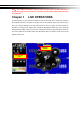
Note: The number of channels, sensors, relays, and split screen, and the resolution in the following figures are for reference. The actual screen output may be different by different models. Chapter 1 LIVE OPERATIONS In the live mode, you may monitor all channels of the DVR, listen to live audio from cameras, and configure the DVR. The DVR can support 4:3 and 16:9 aspect ratios of the screen layout.
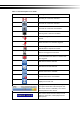
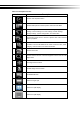
Table 1-1 Icon description in live mode Icon Description Recording of a channel is activated. Live audio of a channel is activated. Live audio of a channel is not activated. Video signal of a channel is available. Event recording of a channel is active in this channel. Motion detection of a channel is triggered. Alarm is triggered of a channel. The number of available alarms depends on models. Alarm is not triggered of a channel. The channel video-loss alarm of a channel has been triggered.
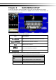
Chapter 2 MAIN MENU SETUP To enter the main menu and set up a DVR, log-in account and user password are required. The default password of the administrator is “123456”. Please check the “Account Setup” for management of other log-in users. Table 2-1 Definition of keys of virtual keyboard Icon Description / Switch between capital letters and lower-case letters. / Switch between numbers and letters Delete the last character。 Enter to verify the password.
There are icons within the configuration pane on the live mode to operate different features of the DVR.
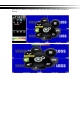
Table 2- 3 Description of icons Icon Description Set the auto sequential menu Set the backup menu to backup video data from DVR HDD. Set the configuration menu to access recording settings, event settings, camera settings, account settings, network settings, storage settings, system configuration, and information Set the time search menu to choose a specific time of the recorded video to playback Set the event search menu to access the list of events recorded by the DVR.
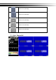
Switch to 13-split display Switch to 16-split display Switch to 20-split display Switch to 25-split display Switch to 32-split display 2-1 Auto Sequential
Item Description Interval The time interval between each channel display All Channels The DVR automatically switches between channels with designated interval. The DVR shows each channel in a single-split mode. Quad-Screen Division The DVR automatically switches between channels with designated interval. The DVR shows channels in 4-split mode. 9-Screen Division The DVR automatically switches between channels with designated interval. The DVR shows channels in 9-split mode.
2-2.2 Select Backup Device Item Description Backup Device Select target device of backup (USB/DVD-RW/remote folder) 。 Status The status of target backup device Free Space The available space in the target backup device. (not available for remote folder backup) Start backup operation. Backup Be sure to calculate the size of backup file BEFORE operating backup.
Do not unplug the USB device or turn off the DVR during the backup process to avoid unrecoverable error. 2-3 Configure Evoke the configuration menu, recording settings, event settings, camera settings, account settings, network settings, storage settings, system configuration, and information. Please refer to chapter 3 for detail.
2-4 Time Search Time search can search for the specific time of recorded data to playback. Note that dates with recording data are marked with a blue box. System will start playing video of specified time slot. Calendar will be shown by using mouse to click on “year” and “month”. Click “date” to display recording time of that specific date with time bar. You can change time (hour/minute/second) or click on a specific pint of time bar by mouse then press “ok”.
Playback configuration Table 2-4 Available keys on the remote control functions in the PLAYBACK mode Button Description ENTER/ MODE Switch to full screen or multi split display. MENU / Turn on/off PAUSE. PLAY Playback at normal speed. / SLOW Playback at slower speed. The speed will be slowed to 1/2, 1/4, 1/8 playback speed, by each pressing of the button till the slowest speed. / Fast rewind. Each press increases the rewind speed to the next level.
Slow playback, speed 1/2x, 1/4x, 1/8x Step playback Zoom-in display, 2x~8x digital zoom Full screen display Quad display 9 screen display 16 screen display Switch to 20-split display Switch to 25-split display Switch to 32-split display If you want to monitor single channel, please double-click the preferred channel.
P.S Can drag a small window 2-5 System Logs The DVR logs events automatically. The event list shows the logged events, event type, event detail, event filter (criteria), and page number of the event list. If the event video is logged, there is a gray video symbol "►" on the left of the event. Move the cursor to event line and press "ENTER", or double-click mouse button, DVR playback this record video related to the event.
2-5.1 Search Criteria The number of event is up to thousands, therefore, to set "search criteria" to facilitate rapid classification of events. If the checkbox of start time and end time is checked, the event list will only display the events within the specific time slot. If the user unchecks some events and press the "OK ", the lists will only shows checked events. If you uncheck the channels, the event list will filter out unchecked the channels.
2-6 PTZ Operation Set up the camera PTZ settings in advance (refer to 3-3.1). Enter the PTZ configuration page, PTZ control panel displays the camera PTZ setting. There is a red cross on the center of the screen. Move the mouse to the Red Cross and hold down the left mouse button to the preferred location of the screen. The DVR will move the camera to the preferred place by placing the preferred place to the center of the screen. On the screen to move in any direction.
location to default point. Press left and right arrow keys to move the camera to the preset locations, and then press era to next preset point. Rotate Video to change the cam- Make the display upside down 2-7 Zoom In the digital zoom mode, users may use the mouse to move the red rectangle of the zoom area. 16:9 display zoom 4:3 display zoom P.S Can drag a small window Item Description Zoom-in the area specified by the red rectangle. Zoom-out the area specified by the red rectangle.
2-8 Shortcut toolbar Real-time monitoring mode, move your mouse over the window function column appears above its fast operation ICON Description User login / logout: Auto lock is used. System Information: The host model, version, IP location, MAC values and hard disk information. Wide screen switching: Switch 4:3 / 16:9 monitor display. Screenshot. Turn on / off recording. Full screen. Options: Change the PC side screen shots, video storage path.
2-8.1 network image quality Option Description Low Quality Single Image Low quality static mode: insufficient bandwidth used for one second about running 1 ~ 2FPS. Low quality Low quality Dynamic mode: According to the DVR recording settings. High-quality High-definition single image under static mode: insufficient bandwidth to use for one second about running 1 ~ 2FPS. High-quality High-definition Dynamic mode: According to the DVR recording settings.
2-8.3 Popup Setup Item Description Event Prompt window displays the channel status。 OSD Display time, HDD status, channel information, channel border. 2-8.4 Relay Setup Option Relay 1 ~ 4 Functional Description Relay J Series x1, N Series x2, B Series x4.
Chapter 3 CONFIGURATION MENU PS. The initialization of new-installed HD is required before recording, please refer to “UTILITY SETUP” for detail.
3-1.1 Continuous Record Item Description Click icon, it will go to the video setting menu of this channel (be- Video low). In settings menu, press to save, press the original video settings menu *1 Record Enable / Disable recording for this channel Resolution to go back to Recording resolution selection *2 FPS Select recording frame rate, from 1 to 30 Quality Recording quality, from 10 to 100.
3-1.1.
3-1.1.2 Event Recording Item Description Record Enable / Disable recording of a channel Resolution Recording resolution selection *2 FPS Select recording frame rate from 1 to 30 Quality Recording quality from 10 to 100. The larger number means the better quality Pre-Alarm Set the record seconds before the event, from 0 to 5. Post-Alarm Set the playback seconds after the event, from 0 to 100 Audio Enable / Disable audio recording of event record of the specified channel.
3-1.2 Schedule Recording Schedule recording can configure recording time by days of a week and hour. With the A, B, C, D four settings, users can set different recording scheme according to different configuration needs. In the day and time grid map, select the schedule time zone, and then press A, B, C, D one of the buttons to specify the video settings. Event Setup Enable or disable motion detection or Sensor function in schedule record.
3-1.2.1 Configuration Item Name Description Change the recording name of the channel For the rest, please refer to 3-1.1 Continuous Record 3-1.2.2 Holiday Configuration The number of holiday is up to 50. When the time comes to the specified holidays, the IVR will start recording according to holiday configuration. Since holidays are different by different country and region, users can setup holidays according to user needs.
3-2 Event Setup 3-2.1 Video Loss 3-2.1.1 Configuration Item Enable Description Enable / Disable video loss detection function 3-2.1.2 Event Handling Item Description Log Write to event log when the video loss event happens. Event Record Select channel for event recording when event occurs.
3-2.1.3Receiver Setup Item Description Enable Specify whether the IVR sends e-mail notice to specified users when an event occurs. Admin / Users Specify the receiver of e-mail notices 3-2.2 Motion Detection 3-2.2.1 Configuration Item Description Enable Enable / Disable the motion detection function of this channel Sensitivity The sensitivity value is from 0 to 100. The higher value means higher sensitivity.
3-2.2.1.1 Motion Area Setup The motion detection has been divided into 22 x18 grids. The default detection area is full screen. The screen is marked in transparent for detection area and grey for disabled area of motion detection. Item Description CH01~ CH16 Selected channel motion detection function。 Mask Mouse Selection Switch between “select” and “deselect” for cursor-dragging function Detect All Area Select entire screen as detection area. Mask All Area Deselect entire detection area.
3-2.3 Sensor ※ Each sensor name can be modified and remotely can enter various languages 3-2.3.1 Configuration Item Enable Polarity Description Enable/Disable sensor N.C: Sensor has not been triggered. When connected, sensor will be turned on N.O: Sensor has been triggered. When connected, sensor status will be turned off 3-2.3.2 Event Handling Please refer to 3-2.1.
3-2.3.3 Receiver Setup Please refer to 3-2.1.3 Receiver Setup 3-2.4 System When the system event occurs, give a notice or warning according to the settings of relay, buzzer, and receiver. If the buzzer box is checked, the buzzer continually beeps for only errors related to the video (such as hard drives can’t write or not install the hard drive). The buzzer does not beep when other system events, such as login, log out or boot, etc., occurs.
3-3 Camera Setup Item Description Name Check the box to Enable/Disable mask function for the camera in the LIVE mode Channel name Timestamp Click on the blue screen to set position of the timestamp. Mask Default is “Auto”. Press the drop-down menu to choose a video formats of your camera if the image is abnormal.
3-3.1 IP Mode Setup Remote Connection Camera Set Protocol IP Port It must be selected to active IP mode Searching IP cam or DVR in the same segment of Network UID User Name Password P2P User ID number of remote device User name of the remote device Password of the remote device Select protocol of IP-based devices. ONVIF protocol is supported IP address of remote device Which port allocate in the IP address. Default is port 80 but you sho uld change it to the correct one. 3-3.1.1 Camera Set Step 1.
Please wait awhile, IP CAM in the same network area are going to be added in the to p of sheet and press “+” to add it to the selection list below. Press “reload” sign in the top right corner to re-search again if there is no device or (a) new added device(s) Step 2-2. Protocol : DVR Mode Choose DVR protocol from the drop-down menu, DVRs in the same network area to b e added in the top of sheet.
Dual Stream, also called “Main Stream”, is higher resolution video stream from the remote for better video quality. Single Stream, also called “Sub Stream”, is lower video resolution from the remote for transferring video easily. Step 4, choose one remote device from the drop-down menu.
Step 5, Press “OK” to leave
3-3.2 PTZ Setup Item Description Enable Click the box to Enable/Disable PTZ function. Protocol Set up the protocol of PTZ cam. The supported protocol are: PELCO-D、PELCO-P、Merit LiLin 1、Merit LiLin 2、SAMSUNG、 LG-MultixE PTZ ID Set up PTZ ID. The valid ID value is from 0 to 255.
3-4 Account Setup You can set the user password and permissions of 10 user accounts (1 admin + 10 users). These different accounts gives users different permissions of IVR features. 3-4.1 Administrator The default admin account and password is “admin” and “123456” Item Description Enable Check to activate the user’s account.
Name Set up the username Password Set up the password. The password can be mixed of letters and numbers and is case-sensitive. e-Mail Set up user email 3-4.2 Other Users Item Description Enable Check to activate the user’s account. Expire Set the expiration date of the user account Name Set up username Password Set up the password. The password can be mixed of letters and numbers and is case-sensitive. e-Mail Set up user email 3-4.2.
※ use of local, remote permissions, respectively, the option must be checked, otherwise it will not work 3-5 Network Setup Item Description DHCP The DVR retrieves from a DHCP server automatically. Static IP Set up a Static IP address of the IVR. PPPoE Set up the username and password for PPPoE connection. 3G Setup Set up the login configuration of 3G connection HTTP Setup Set up the HTTP configuration for remote access. DDNS Set up the DDNS configuration.
3-5.1 Networking Setup There are three ways to connect to the network. 3-5.1.1 DHCP Setup When DHCP is selected, IP address will be assigned by DHCP server automatically. Notice: The IP address shown in this page is not the IP address obtained from the DHCP server. The IP obtained from the DHCP server is shown in the System Information Page. 3-5.1.2 Static IP Setup Setup Static IP for network connection, the following information is required.
(Note: The correct DNS address must be entered for DDNS function). 3-5.1.3 PPPoE Setup Select PPPoE for network connection, the following information is required. Item Description Enable Enable / Disable PPPoE function。 User Enter user name provided by ISP Password Enter password provided by ISP 3-5.1.4 3G Setup Using the USB 3G dongle to access the network PS: only specific chip of 3G dongle is supported and the 3G dial-up features may not be compatible to some ISPs.
Item Description Enable Enable / Disable 3G function. Dial Number Dial-up Number, offer by the ISP PIN Enter SIM card password APN Enter “internet” or other value offered by the ISP. User Enter ISP username Password Enter ISP password 3-5.1.
HTTP Setup Item Description Enable Check to enable HTTP server. Users can remotely access into the IVR over the network if the HTTP function is activated. Port Enter a valid port value from 1 up to 65535. The default value is 80. Apply Key Input P2P Access Key for P2P 3-5.
Item Description Enable Enable / Disable DDNS function. Enter the registered DDNS Server: ez- dns.com、i-dvr.net、dyndns.org Server ez- dns.com、i-dvr.net Supports automatic assignment DDNS When these two DDNS service, The system will automatically bring up to C + DVR Mac Address last six yards at the beginning of a host site, Such as the Mac end of the six yards of FD5CCD, Then bring out the host site at CFD5CCD.i-dvr.net or CFD5CCD.ez-dns.com Host Enter the full DDNS address.
3-5.4 Mail Setup The Mail Setup tab controls the email-sending configuration when the IVR needs to send e-mail to specified users. Item Description Enable Check the box to enable/disable E-mail Notification function SMTP Server Set up SMTP Server name and port User Enter to set up the username. Password Enter to set up the password. Sender’s e-Mail Enter to set up e-mail address of the sender.
3-5.5 FTP Setup Item Description Enable Check the box to enable/disable FTP function Server Set up FTP Server name and port User Enter to set up the username. Password Enter to set up the password.
3-6 Storage Setup 3-6.1 HDD Setup ※ Click the status bar to change the attributes of the hard disk Item Description Video Preservation (Hours) Setup the video preservation period. Recorded video will be deleted automatically after expiry of preservation period.
3-6.2 USB Flash Derive Setup Item Description Model Display USB flash drive model Free/Capacity Display USB flash drive capacity (Free/Capacity ) 3-6.
3-7 System Setup Item Description IVR Name The name of IVR to be shown while users login from remote site. Language Specify the OSD language. Video Format Detection Specify the format of video signal (auto-detect, NTSC, PAL). The configuration requires DVR reboot to take effect 3-7.1 Auto Lock Item Description Enable Enable / Disable Auto Lock Timeout(Seconds) Set the number of seconds to wait. It there is no action, the panel will be automatically locked and the IVR logs out current user.
3-7.3 Date/Time Setup Item Description Hour Format 12HOURS/ 24HOURS Date Format MM-DD-YY/DD-MM-YY/YY-MM-DD 3-7.3.1 Time zone Item Description Time Zone Setup Set up the time zone of the IVR, from GMT - 13 ~ GMT+ 13。 Daylight Saving Time Enable / Disable Daylight Saving Time 3-7.3.2 Daylight Saving Time Setup Item Description Beginning Setup the beginning time of Daylight Saving Time. Ending Setup the ending time of Daylight Saving Time.
3-7.3.3 Change Date and Time Setup date and time of the IVR.
3-7.4 Monitor Setup This feature is only support "Maya v2" series models. Users have to decide which one is the main screen, which is the second screen. In the setting can be used when there are three configurations. In duplicate mode, both monitors display the same content. In the HDMI (1) VGA (2) mode, HDMI will be the screen 1, VGA will be the screen 2. In VGA (1) HDMI (2) VGA mode, VGA will be the screen 1, HDMI will be the screen 2. BNC output terminals are the same as with the contents of a screen 1.
Monitor setup Item Description 1、2 set the main screen (1), the second screen (2) screen display setup menu Resolution selection screen resolution Border Color Set the color of border Luminance Setting brightness, from 0 to 100. Contract Setting screen display color contrast, from 0 to 100. Saturation Setting screen display color saturation from 0 to 100.
3-7.5 Input Setup The Input Setup allows users’ setup input device (Key Tone, Remote control, Panel, Mouse, Keyboard, Touch screen). Item Key Tone Description Enable / Disable Key Tone. 3-7.5.1 Remote Control Setup Item Description Enable Enable / Disable remote control. IR ID Default ID is 0. IVR is controlled by standard remote control; For one to many remote control, remote control on the number corresponding to the IVR numbers (DVR1 → IC01, DVR2 → IC02). Test Enable / Disable test function.
3-7.5.2 Panel Setup Item Description Test Enable / Disable panel button test function. Press Key Display information of the pressed key. 3-7.5.3 Mouse Setup Item Speed Description Setup the mouse cursor speed. The right side of the slider means faster mouse speed.
3-7.5.4 PTZ Keyboard Setup Item Description RS-485 ID RS-485 ID, valid values range from 1 to 64 RS-485 Baud rate RS-485 Baud rate from 2400, 4800, 9600, 19200 Keyboard Select PTZ Keyboard Test Enable / Disable keyboard test function Press Key Display press key information 3-7.5.5 Touch Screen Setup Detects the touch screen Users can calibrate the touch screen which needs recalibration.
3-7.6 Utility Setup Item Description Export Configuration Export IVR configuration to a USB flash drive or a remote PC. Import Configuration Import configuration from a USB flash drive or a remote PC to IVR. Reset Configuration Reset system configuration. Export Logs Save IVR system log to a USB flash drive or a remote PC. Clear Logs Clear all IVR system log. Upgrade IVR firmware through a USB drive.
3-7.6.1 Export Configuration There are several options for target storage of IVR configuration. a. Export to a USB Flash Drive: The default filename is “dvr.cfg” b. Save *.
3-7.6.2 Import Configuration Import configuration to the IVR from a USB drive or a remote computer. a. Import from USB Flash Drive: Import the configuration from a USB flash drive. b. Open *.
3-7.6.3 Reset Configuration Reset the IVR to default settings. 3-7.6.4 Export Logs a. Export to USB Flash Drive: Export logs to a USB flash drive. The default file name is “log.csv” b.Save *.
3-7.6.5 Clear Logs Clear the system logs.
3-7.6.6 Upgrade Firmware Notice! DO NOT TURN OFF POWER OR UNPLUG USB DEVICE DURING THE UPGRADE because that may cause incomplete firmware upgrade and damage the IVR. a. Upgrade from USB Flash Drive...: Choose the firmware from USB flash drive to upgrade b.
3-8 System Information 3-8.1 IVR Information Item Model Version Description IVR model name and video type IVR firmware version 3-8.2 Network Information Item Description IVR IP address If there is no network connection, it will show "Network is not connected. The IVR MAC address IP MAC 3-8.
3-8.4 S.M.A.R.
REMOTE SOFTWARE INSTALLATION and SETUP The IVR allows users remotely access and control the DVR from a PC by 「iWatchDVR」or IE v6.0 or above. p.s. The DVR currently supports Windows 7、Windows 8/8.1、Windows 10. 3-9 Application Software Connection Step 1:Enter the IP address of IVR in IE browser. Step 2:Windows as below will show up. Please enter the user name and password. Default user name and password is admin/123456.
Step 3:Click on the link ”iWatchDVR for Windows XP/Vista/7/8” to start downloading the AP software. Step 4:The program can be run directly, or save the program to the remote PC and execute later. If you choose to run the software, Start window will be shown up. Please enter information of login IVR: IP, Port, Username and Password.
The drop-down menu can be used to record IP address. Press “Clear” to clear IP address.
3-10 IE Connection Step 1:Enter the IP address of IVR in IE browser. The address appeared in this image is only for demonstration. Actual address is depending on the setup of on-site IVR Step 2:Windows as below will show up. Please enter the user name and password. Default user name and password is admin/123456. Other related setup about user account and password, please check “Account Setup. “ The user name and password appeared in this image is only for demonstration.
Step 4:IVR images appear.。Default is 4:3 display. Table 3-10.1 System Requirements CPU Intel Core 2 Due above OS Microsoft Windows 7, Windows Vista, Windows XP SP2 above RAM 4G above VGA Card Needed to support DirectX9.0 (Above) Note 1 Anti-virus softThe TCP destination port 80 should be available. ware (firewall) Others DirectX 9.0 above Note 1: Known VGA card that support DirectX9.
3-11 APP Software Connection (Android for example) 1. Go “Google Play” or APP store (iOS) to download the “SoCatch”. 2. Press the “New” icon in the upper right corner to add a new connection. 3. Give a Name of this connection and input network address、 port (default:80)、Username (default:admin) and Password (Default : 123456), or press “Lan Search IP” to search DVR/IP CAM IP in the same network. 4.
5. Multiscreen can be chose in Live view 6. Video quality 、mute and unmute audio 7. Searching by Time or Log files 8. You can search by time or event (log type) in the log search.
9. Highlights in the monthly calendar are those days which has video recording. Pick one of them and choose a start time to watch the recording. 10. Play Rewind、Forward、Pause and Start/Stop 11. Mute and unmute the audio 12.
13. Choose a section of the recoding and back it down to your device i. Mark In/out : Press “Mark In” to set start time and wait for a while then press “Mark Out” to set stop backup time. ii. Go Backup:After setting duration and channel, press “Calculate” key to calculate required space, then press “Download”. *Note: DO NOT execute another application program during backup download. 14. Other settings, such as PTZ、Relay、Zoom…etc. 15.
16. Backup list:All the backup files should be listed on the backup list. Press any file on the list to execute the file.
3-12 P2P Connection Setup How to Setup 1. On your DVR/IVR, please go to Network Setup page: Main control panel => Configuration => Network Setup 2. On lower part of Network Setup page, please input P2P Access Key for P2P and press Apply button. Please press OK button on lower part of Network Setup page and return to Configuration level. 3.
For computer use, please login iWatchDVR. On prompting interface, please input P2P Access Key in Host field, input / modify the rest of fields as appropriate Click on Connect button 4. For mobile device (i.e., smart phone and tablet) users, please login APP “Socatch” Click ‘+’ (iOS) / ‘New’ (Android) icon on upper right corner to add a new connection. 5. Click on Scan QR code button as shown on following picture.
6. Please scan QR code on DVR’s System Information page 7. Access key information will be shown on Host field Input / modify the rest of fields as appropriate. Click on Save button on upper right corner.