
User manual

DIGITAL-LOGIC AG MSM800SEV/SEL/BEV/XEV/XEL Detailed Manual V1.5
49
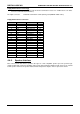
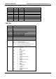
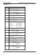
CMOS Map continued...
Location Description
1Fh Byte 0
Bits 7-0 = Lower 8 bits of Cylinders
20h Byte 1
Bits 7-2 = Lower 6 bits of Landing Zone
Bits 1-0 = Upper 2 bits of Cylinders
21h Byte 2
Bits 7-4 = Lower 4 bits of Write Precompensation
Bits 3-0 = Upper 4 bits of Landing Zone
22h Byte 3
Bits 7-6 = Reserved
Bits 5-0 = Upper 6 bits of Write Precompensation
23h Byte 4
Bits 7-0 = Number of Heads
24h Byte 5
Bits 7-0 = Sectors Per Track
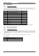
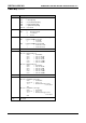
25h - 2Ah Custom Drive Table 1
These 6 Bytes (48 bits) contain the following data:
Cylinders 10bits range 0-1023
Landing Zone 10bits range 0-1023
Write Precompensation 10bits range 0-1023
Heads 08bits range 0-15
Sectors/Track 08bits range 0-254
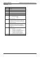
25h Byte 0
Bits 7-0 = Lower 8 bits of Cylinders
26h Byte 1
Bits 7-2 = Lower 6 bits of Landing Zone
Bits 1-0 = Upper 2 bits of Cylinders
27h Byte 2
Bits 7-4 = Lower 4 bits of Write Precompensation
Bits 3-0 = Upper 4 bits of Landing Zone
28h Byte 3
Bits 7-6 = Reserved
Bits 5-0 = Upper 6 bits of Write Precompensation
29h Byte 4
Bits 7-0 = Number of Heads
2Ah Byte 5
Bits 7-0 = Sectors Per Track
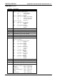
2Bh Boot Password
Bit 7 = Enable/Disable Password
0 = Disable Password
1 = Enable Password
Bits 6-0 = Calculated Password
2Ch SCU Password
Bit 7 = Enable/Disable Password
0 = Disable Password
1 = Enable Password
Bits 6-0 = Calculated Password
Continued...