
User manual


DIGITAL-LOGIC AG MSB900/L Detailed Technical Manual V1.0
30
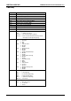
CMOS Map
Location Description
00h Time of day (seconds) specified in BCD
01h Alarm (seconds) specified in BCD
02h Time of day (minutes) specified in BCD
03h Alarm (minutes) specified in BCD
04h Time of day (hours) specified in BCD
05h Alarm (hours) specified in BCD
06h Day of week specified in BCD
07h Day of month specified in BCD
08h Month specified in BCD
09h Year specified in BCD
0Ah Status Register A
Bit 7 = Update in progress
Bits 6-4 = Time based frequency divider
Bits 3-0 = Rate selection bits that define the periodic
interrupt rate and output frequency.
0Bh Status Register B
Bit 7 = Run/Halt
0 Run
1 Halt
Bit 6 = Periodic Timer
0 Disable
1 Enable
Bit 5 = Alarm Interrupt
0 Disable
1 Enable
Bit 4 = Update Ended Interrupt
0 Disable
1 Enable
Bit 3 = Square Wave Interrupt
0 Disable
1 Enable
Bit 2 = Calendar Format
0 BCD
1 Binary
Bit 1 = Time Format
0 12-Hour
1 24-Hour
Bit 0 = Daylight Savings Time
0 Disable
1 Enable
0Ch Status Register C
Bit 7 = Interrupt Flag
Bit 6 = Periodic Interrupt Flag
Bit 5 = Alarm Interrupt Flag
Bit 4 = Update Interrupt Flag
Bits 3-0 = Reserved
0Dh Status Register D
Bit 7 = Real Time Clock
0 Lost Power
1 Power
Continued...