
User manual


DIGITAL-LOGIC AG MSB900/L Detailed Technical Manual V1.0
33
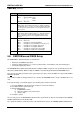
CMOS Map continued...
Location Description
22h
Byte 3
Bits 7-6 = Reserved
Bits 5-0 = Upper 6 bits of Write Precompensation
23h
Byte 4
Bits 7-0 = Number of Heads
24h
Byte 5
Bits 7-0 = Sectors Per Track
25h - 2Ah Custom Drive Table 1
These 6 Bytes (48 bits) contain the following data:
Cylinders 10bits range 0-1023
Landing Zone 10bits range 0-1023
Write Precompensation 10bits range 0-1023
Heads 08bits range 0-15
Sectors/Track 08bits range 0-254
25h
Byte 0
Bits 7-0 = Lower 8 bits of Cylinders
26h
Byte 1
Bits 7-2 = Lower 6 bits of Landing Zone
Bits 1-0 = Upper 2 bits of Cylinders
27h
Byte 2
Bits 7-4 = Lower 4 bits of Write Precompensation
Bits 3-0 = Upper 4 bits of Landing Zone
28h
Byte 3
Bits 7-6 = Reserved
Bits 5-0 = Upper 6 bits of Write Precompensation
29h
Byte 4
Bits 7-0 = Number of Heads
2Ah
Byte 5
Bits 7-0 = Sectors Per Track
2Bh Boot Password
Bit 7 = Enable/Disable Password
0 = Disable Password
1 = Enable Password
Bits 6-0 = Calculated Password
2Ch SCU Password
Bit 7 = Enable/Disable Password
0 = Disable Password
1 = Enable Password
Bits 6-0 = Calculated Password
2Dh Reserved
2Eh High Byte of Checksum - Locations 10h to 2Dh
2Fh Low Byte of Checksum - Locations 10h to 2Dh
30h Extended RAM (kB) detected by POST - Low Byte
31h Extended RAM (kB) detected by POST - High Byte
32h BCD Value for Century
Continued...