
User manual


DIGITAL-LOGIC AG MSB900/L Detailed Technical Manual V1.0
34
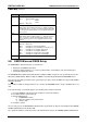
CMOS Map continued...
Location Description
33h Base Memory Installed
Bit 7 = Flag for Memory Size
0 = 640kB
1 = 512kB
Bits 6-0 = Reserved
34h
Minor CPU Revision
Differentiates CPUs within a CPU type (i.e., 486SX vs 486 DX,
vs 486 DX/2). This is crucial for correctly determining CPU input
clock frequency. During a power-on reset, Reg DL holds minor
CPU revision.
35h
Major CPU Revision
Differentiates between different CPUs (i.e., 386, 486, Pentium).
This is crucial for correctly determining CPU input clock fre-
quency. During a power-on reset, Reg DH holds major CPU
revision.
36h Hotkey Usage
Bits 7-6 = Reserved
Bit 5 = Semaphore for Completed POST
Bit 4 = Semaphore for 0 Volt POST (not currently used)
Bit 3 = Semaphore for already in SCU menu
Bit 2 = Semaphore for already in PM menu
Bit 1 = Semaphore for SCU menu call pending
Bit 0 = Semaphore for PM menu call pending
40h-7Fh
Definitions for these locations vary depending on the chipset.
5.8. EEPROM saved CMOS Setup
The EEPROM has different functions, as listed below:
• Backup of the CMOS-Setup values.
• Storing system information (i.e., version, production date, customization of the board, CPU type).
• Storing user/application values.
The EEPROM will be updated automatically after exiting the BIOS setup menu. The system will operate also
without any CMOS battery. While booting, the CMOS is automatically updated with the EEPROM values.
Press the Esc-key while powering on the system before the video shows the BIOS message and the CMOS
will not be updated.
This would be helpful, if wrong parameters are stored in the EEPROM and the setup of the BIOS does not
start.
If the system hangs or a problem appears, the following steps must be performed:
1. Reset the CMOS-Setup (disconnect the battery for at least 10 minutes).
2. Press Esc until the system starts up.
3. Enter the BIOS Setup:
a) load DEFAULT values
b) enter the settings for the environment
c) exit the setup
4. Restart the system.
The user may access the EEPROM through the INT15 special functions. Refer to that chapter in the GEODE
LX800-LX900 manual on the Product CD.
The system information is read-only and uses the SFI functions. Refer to the GEODE LX800-LX900 manual.