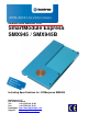
Detailed USER MANUAL FOR: SmartModule Express SMX945 / SMX945B Including Specifications for: COMexpress SMX945 Nordstrasse 11/F CH - 4542 Luterbach Tel.: ++41 (0)32 681 58 00 Fax: ++41 (0)32 681 58 01 Homepage: http://www.digitallogic.com Support: http://support.kcc-ag.
Kontron Compact Computers AG SMX945 Detailed Manual V1.1 For internal use only: File: Path: SMX945_Detailed_V1.1.doc R:\HANDBUCH\smart\SMX945\SMX945_Detailed_V1.1.doc COPYRIGHT 2011 BY KONTRON COMPACT COMPUTERS AG This publication is protected by copyright and all rights are reserved.
Kontron Compact Computers AG SMX945 Detailed Manual V1.1 Table of Contents 1. PREFACE .....................................................................................................................................................5 1.1. Trademarks ..................................................................................................................................... 5 1.2. Disclaimer ........................................................................................................
Kontron Compact Computers AG SMX945 Detailed Manual V1.1 6.2.1. Passive/Active Heat Sink....................................................................................................... 33 6.2.2. SODIMM-DDR2 RAM ............................................................................................................ 34 6.3. COMexpress Connector Description ......................................................................................... 36 6.3.1. Signal Terminology Descriptions ..........
Kontron Compact Computers AG SMX945 Detailed Manual V1.1 1. PREFACE The information contained in this manual has been carefully checked and is believed to be accurate; it is subject to change without notice. Product advances mean that some specifications may have changed. Kontron AG assumes no responsibility for any inaccuracies, or the consequences thereof, that may appear in this manual.
Kontron Compact Computers AG 1.5. SMX945 Detailed Manual V1.1 Recycling Information All components within this product fulfill the requirements of the RoHS (Restriction of Hazardous Substances Directive). The product is soldered with a lead free process. 1.6. Technical Support 1. Contact your local Kontron Technical Support, in your country. 2. Use the Internet Support Request form at http://support.kcc-ag.
Kontron Compact Computers AG 1.8. SMX945 Detailed Manual V1.1 Explanation of Symbols CE Conformity This symbol indicates that the product described in this manual is in compliance with all applied CE standards. Caution, Electric Shock! This symbol and title warn of hazards due to electrical shocks (> 60V) when touching products or parts of them. Failure to observe the precautions indicated and/or prescribed by the law may endanger your life/health and/or result in damage to your equipment.
Kontron Compact Computers AG 1.9. SMX945 Detailed Manual V1.1 Applicable Documents and Standards The following publications are used in conjunction with this manual. When any of the referenced specifications are superseded by an approved revision, that revision shall apply. All documents may be obtained from their respective organizations. Advanced Configuration and Power Interface Specification Revision 2.
Kontron Compact Computers AG SMX945 Detailed Manual V1.1 Smart Battery Data Specification Revision 1.1, December 11, 1998. www.sbs-forum.org System Management Bus (SMBus) Specification Version 2.0, August 3, 2000 Copyright © 1994, 1995, 1998, 2000 Duracell, Inc., Energizer Power Systems, Inc., Fujitsu, Ltd., Intel Corporation, Linear Technology Inc., Maxim Integrated Products, Mitsubishi Electric Semiconductor Company, PowerSmart, Inc., Toshiba Battery Co. Ltd.
Kontron Compact Computers AG SMX945 Detailed Manual V1.1 RoHS is often referred to as the "lead-free" directive but it restricts the use of the following substances: Lead Mercury Cadmium Chromium VI PBB and PBDE The maximum allowable concentration of any of the above mentioned substances is 0.1% (except for Cadmium, which is limited to 0.01%) by weight of homogeneous material.
Kontron Compact Computers AG SMX945 Detailed Manual V1.1 1.12. Swiss Quality 100% Made in Switzerland This product was not manufactured by employees earning piecework wages This product was manufactured in humane work conditions All employees who worked on this product are paid customary Swiss market wages and are insured ISO 9000:2001 (quality management system) 1.13.
Kontron Compact Computers AG SMX945 Detailed Manual V1.1 2. OVERVIEW 2.1. Standard Features The smartModuleExpress945 is a miniaturized PC system on chip unit incorporating the major elements of a PC/AT compatible computer. It includes standard PC/AT compatible elements, such as: Powerful Core Duo, Core 2 Duo, Core Solo CPU DDR2 SODIMM socket for 256MByte to 2GByte (SMX945), RAM-Module 1GB DDR2 RAM soldered onboard, only SMX945B DDR2 SODIMM socket for 256MByte to 2GByte RAM-Module (SMX945B max.
Kontron Compact Computers AG 2.2. SMX945 Detailed Manual V1.1 Unique Features EEPROM for setup and configuration UL approved parts Remote Function Thermal Interface with a very low thermal resistance (copper core) Very ruggedized, withstands highest mechanical vibration and shock Very low power consumption no active cooling required Extended wide range power input for single 5Volt supply applications Power Management Microcontroller 2.3.
Kontron Compact Computers AG 2.4. SMX945 Detailed Manual V1.1 Block Diagram * This function is disabled. A Macrovision license is required to enable it.
Kontron Compact Computers AG 2.5. SMX945 Detailed Manual V1.1 Specifications CPU CoreDuo / Celeron M Clock st 1 Level Cache nd 2 Level Cache Technology VCCCore @ 1.6GHz VCCCore @ 0.6GHz VCCCore @ deep sleep CPU-Bus AGTL+ Termination FSB Specification Intel Core Duo L2400 LV 2x 1.66GHz with 2MB L2-cache Intel Core 2 Duo L7400 LV 2x 1.66GHz with 4MB L2-cache 1GHz up to 1.86GHz 2x 32kByte 1, 2, 4 MByte (on die) 65nm 1.308V 0.844V 0.
Kontron Compact Computers AG Intel 945GME Graphics PEG PEG Controller Alternative to the internal graphic controller multiplexed with the SDVO signals Support Mode Voltage Signals Intel 82801DBM (ICH7DH) PCI-Bus EIDE-Bus SATA-Bus USB V2.0 APIC SMB FWH LPC SMX945 Detailed Manual V1.1 Specification PEG 16 lanes 1.5Volt Differential 2.5Gbit/sec Sound IRQ Controller Timers Power Management Specification Supports PCI 2.
Kontron Compact Computers AG Physical Characteristics Dimensions Weight PCB Thickness PCB Layer Operating Environment Relative Humidity Vibration Shock Operating Temperature Maximum Copper Temperature Storage Temperature Specification Length: 117 mm +/- 0.1mm Depth: 70 mm +/- 0.1mm Height: 15 mm +/- 0.2mm (with 5mm bus connectors) 18 mm +/- 0.2mm (with 8mm bus connectors) The connector height is selected by the connector on the carrier board. 120 grams / 12 ounces 1.6 mm / 0.
Kontron Compact Computers AG 2.7. SMX945 Detailed Manual V1.1 Product Pictures: 2.7.1. SMX945: 2.7.2.
Kontron Compact Computers AG 2.8. SMX945 Detailed Manual V1.1 Thermoscan 2.8.1. SMX945 – CPUs CPU with 512MB-RAM Core Duo L7400 Core Duo L2400 Celeron M 423 Celeron M 440 2.8.2. Desktop WIN-XP 1.2A / 6W 1.2A / 6W 1.4A / 7W 1.9A / 10W 100% workload 4.4A / 22W 4.8A / 24W 2.5A / 13W 4.6A / 23W Standby 1.4A / 7W 1.4A / 7W 1.4A 7 7W 1.
Kontron Compact Computers AG SMX945 Detailed Manual V1.1 3. PC FUNCTIONAL DESCRIPTION 3.1. Power Input The SMX945 module uses a single main power rail with a nominal value of +12V. Kontron Compact Computers has expanded the 12Volt input to a wide-range input, working between 5Volt and 18Volt. Main supply: 5.0Volt (-0.1V) to 18Volt ( +0V) with 20-30Watt depending on the processor.
Kontron Compact Computers AG 3.1.2. SMX945 Detailed Manual V1.1 Battery Backed Clock (RTC) An AT compatible date/time clock is located within the chipset. The device also contains a CMOS static RAM, compatible with that in standard ATs. System configuration data is normally stored in the clock chip's CMOS RAM in a manner consistent with the convention used in other AT compatible computers. Connect an external Lithium battery of 3.0V-3.6V to the RTC pin.
Kontron Compact Computers AG 3.3. 3.3.1. SMX945 Detailed Manual V1.1 BIOS ROM-BIOS An EPROM with 8bit wide data access normally contains the board's AT compatible ROM-BIOS. The BIOS takes an E82802AC8 EPROM (or equivalent) device on the LPC-Bus. The board's wait-state control logic automatically inserts four memory wait states in all CPU accesses to this (socket).
Kontron Compact Computers AG 3.4. SMX945 Detailed Manual V1.1 CMOS RAM Map Systems based on the industry-standard specification include a battery backed Real Time Clock chip. This clock contains at least 64Bytes of non-volatile RAM. The system BIOS uses this area to store information including system configuration and initialization parameters, system diagnostics, and the time and date. This information remains intact even when the system is powered down. The BIOS supports 128Bytes of CMOS RAM.
Kontron Compact Computers AG 3.6. SMX945 Detailed Manual V1.1 Graphics Controller The Intel 945GM Express Chipset The GMCH IGD provides a highly integrated graphics accelerator delivering high performance 2D, 3D and video capabilities. With its interfaces to UMA using a DVMT configuration, an analog display, a LVDS port and two digital display ports (e.g. flat panel), the GMCH can provide a complete graphics solution. The GMCH also provides 2D hardware acceleration for block transfers of data (BLTs).
Kontron Compact Computers AG SMX945 Detailed Manual V1.1 5. LED CRITERIA: LED D26 D31 Color Green Green Function Run OK 3.3Volt OK The Power & Control LEDs on the SMX945PC There are 2 LEDs located on the top side of the smartModule: 1. The green Power LED a. Indicates that the 3.3V core supply for the CPU is OK. b. This LED must light as soon as the external 5V power supply is available. 2. The green Reset/Run LED OFF: The module is in the Reset state which means there is no operation.
Kontron Compact Computers AG SMX945 Detailed Manual V1.1 6. DESIGN-IN WITH THE SMARTMODULE 6.1.
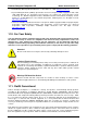
Kontron Compact Computers AG SMX945 Detailed Manual V1.1 Attention! When using an active/passive heatsink that is not from KCC, be very careful! The maximum depth the screws can go into the product is 3mm or the smartModule will be destroyed! 6.1.1.
Kontron Compact Computers AG SMX945 Detailed Manual V1.
Kontron Compact Computers AG 6.1.2. SMX945 Detailed Manual V1.1 Connector Placement & Pin Definition on the Carrier Board Top View of the PCB: Remarks: 1. All dimensions in millimeters. 2. For the carrier board, use the Pin Definition A1/B1/C1/D1 for the plug. 3. The receptacle is mounted on the SMX945/915.
Kontron Compact Computers AG SMX945 Detailed Manual V1.1 6.1.3. Connector Placement on the Carrier Board 6.1.4.
Kontron Compact Computers AG 6.1.5. SMX945 Detailed Manual V1.
Kontron Compact Computers AG 6.1.6. SMX945 Detailed Manual V1.1 Dimensions of the Carrier Board Connector SMX-CON8: Standard height: KCC part number: AMP/Tyco: 8.0mm 807138 8-6318491-6 (components placed below the smartModule total a maximum 2.0mm) 6.1.7. Component Heights between Module and Carrier Board Parts mounted on the back side of the module (in the space between the bottom surface of the module PCB and the carrier board) should have a maximum height of 8.0mm.
Kontron Compact Computers AG 6.2. 6.2.1. SMX945 Detailed Manual V1.1 Assembly / Disassembly Passive/Active Heat Sink Attention! When using an active/passive heatsink that is not from KCC, be very careful! The maximum depth the screws can go into the product is 3mm or the smartModule will be destroyed! The photo on the left shows the basic SMX945 with active heat sink. The photo below shows a passive heat sink. Assembly is the same except Step 3 is not required for a passive heat sink.
Kontron Compact Computers AG SMX945 Detailed Manual V1.1 Step 3: Plug the fan into the electric connection on the host board. For example: On the MSEBX945 V1.0: Connector X207 Pin1 (GND) and Pin2 (FAN1_PWR) or Connector X208 Pin1 (GND) and Pin2 (FAN2_PWR) On the MSM945: Connector X205 Pictured: electric connection on the MSEBX945. 6.2.2. SODIMM-DDR2 RAM Step 1: In the case of an active heat sink, remove the electric fan connector. This step is not required for a passive heat sink.
Kontron Compact Computers AG SMX945 Detailed Manual V1.1 Step 3: Remove the 2 screws from the SODIMM cover and dismantle the cover very carefully. Slide the cover to the side and gently lift it away from the casing. Screw Type: Cylinder hexagon socket type screw M2x4mm / BN11 DIN912 ISO 4762 Tool: Hexagon head socket wrench no. 1.5 Step 4: Using your thumbnails, gently push the clips holding the RAM module in place toward the outside. There will be a slight "click" and the RAM will flip up at an angle.
Kontron Compact Computers AG 6.3. SMX945 Detailed Manual V1.1 COMexpress Connector Description 6.3.1. Signal PU PD I/O 3.3V I/O 5V I 3V I 5V I/O 3.3VSB O 3V O 5V P D DDC PCIE SATA LVDS LAN TPM Signal Terminology Descriptions Description Internally implemented Pull up resistor Internally implemented Pull down resistor Bi-directional signal 3.3V tolerant Bi-directional signal 5V tolerant Input 3.3V tolerant Input 5V tolerant Input 3.3V tolerant, active in standby state Output 3.
Kontron Compact Computers AG 6.3.2. SMX945 Detailed Manual V1.1 COMexpress Connector Pinout COMexpress type 2 (BUS on the smartModuleExpress 945) Connectors A / B: Pins 1-55 Pin A1 A2 A3 A4 A5 A6 A7 A8 A9 A10 A11 A12 A13 A14 A15 A16 A17 A18 A19 A20 A21 A22 A23 A24 A25 A26 A27 A28 A29 A30 A31 A32 A33 A34 A35 A36 A37 A38 A39 A40 A41 A42 A43 A44 A45 A46 A47 A48 A49 A50 A51 A52 A53 A54 A55 Group Volt LAN LAN LAN LAN LAN LAN LAN LAN LAN D D 3.3V 3.3V D D 3.
Kontron Compact Computers AG SMX945 Detailed Manual V1.1 COMexpress type 2 (Bus on smartModuleExpress 945) Connectors A / B: Pins 56-110 Pin Group A56 A57 A58 A59 A60 A61 A62 A63 A64 A65 A66 A67 A68 A69 A70 A71 A72 A73 A74 A75 A76 A77 A78 A79 A80 A81 A82 A83 A84 A85 A86 A87 A88 A89 A90 A91 A92 A93 A94 A95 A96 A97 A98 A99 A100 A101 A102 A103 A104 A105 A106 A107 A108 A109 A110 PCIEX4 D PCIEX3 PCIEX3 D D PCIEX2 PCIEX2 D D PCIEX1 PCIEX1 D D Volt Length Signal 3.
Kontron Compact Computers AG SMX945 Detailed Manual V1.1 COMexpress type 2 (BUS on the smartModuleExpress 945) Connectors C / D: Pins 1-55 Pin Group C1 C2 C3 C4 C5 C6 C7 C8 C9 C10 C11 C12 C13 C14 C15 C16 C17 C18 C19 C20 C21 C22 C23 C24 C25 C26 C27 C28 C29 C30 C31 C32 C33 C34 C35 C36 C37 C38 C39 C40 C41 C42 C43 C44 C45 C46 C47 C48 C49 C50 C51 C52 C53 C54 C55 Volt IDE IDE IDE IDE IDE IDE IDE IDE IDE 3.3V 3.3V 3.3V 3.3V 3.3V 3.3V 3.3V 3.3V 3.3V IDE IDE IDE PCI PCI PCI PCI PCI PCI 3.3V 3.3V 3.3V 3.
Kontron Compact Computers AG SMX945 Detailed Manual V1.
Kontron Compact Computers AG 6.3.3. SMX945 Detailed Manual V1.1 COMexpress Connector Specifications The Kontron Compact Computers smartModuleX945 module connectors are surface-mounted, 0.5mm pitch, 220pin connectors.
Kontron Compact Computers AG 6.3.4. SMX945 Detailed Manual V1.1 SDVO / PEG Multiplexed Signals The Kontron Compact Computers (KCC) smartModuleX945 uses the upper PEG signals to multiplex the two SDVO channels. If the SDVO is in use, the PEG function is not available. Intel allows, with the P45CM, multiplexing the SDVO on the lower or, alternatively, on the upper PEG lines. KCC's implementation for multiplexing the upper PEG lines are defined in the table below.
Kontron Compact Computers AG 6.4. SMX945 Detailed Manual V1.1 Signal Loss COM Express™ module and carrier board insertion-loss budgets for the PCI Express, SATA, USB and GBE interfaces are presented in the following sections. These budgets were formulated to be compatible with the relevant source specifications. The source specifications vary in their treatment of insertion-loss parameters.
Kontron Compact Computers AG 6.5. 6.5.1. SMX945 Detailed Manual V1.1 Layout of High Speed Signals: Design Rules for PCIexpress Point-to-point, match per data pair only TX must be AC coupled up to 12" long, 0.3dB loss per inch max. 13.
Kontron Compact Computers AG 6.5.2. SMX945 Detailed Manual V1.
Kontron Compact Computers AG 6.5.3. SMX945 Detailed Manual V1.
Kontron Compact Computers AG 6.6. SMX945 Detailed Manual V1.1 Signal Descriptions Signal VCC Description Power Supply +5VDC ±5% I/O P GND 3.3V Power Ground Power Supply +3.3VDC P P NC SERIRQ PCICLK1-4 REQ0-3# Not Connected Serial Interrupt request Clock output Bus request N.A. I 3.3V O 3.3V I 3.3V PU 8k2 3.
Kontron Compact Computers AG SMX945 Detailed Manual V1.1 The PCI Local Bus Specification requires that: PCI clocks be synchronous within a 2 ns window at the destination devices the maximum propagation delay for the clock be 10 ns PCI slot-based add-on cards implement a PCI clock trace length of 2.
Kontron Compact Computers AG Signal USB0 USB0# SMX945 Detailed Manual V1.1 Description USB Port 0, data + or D+ USB Port 0, data - or D- I/O Termination I/O 3.3V I/O 3.3V Remarks USB 2.0 compliant USB 2.0 compliant USB Port 7, data + or D+ USB Port 7, data - or D- I/O 3.3V I/O 3.3V USB 2.0 compliant USB 2.
Kontron Compact Computers AG Signal SATA0_RX+ SATA0_RXSATA0_TX+ SATA0_TX- Description Serial ATA channel 0 Receive Input differential pair Serial ATA channel 0 Transmitter Output differential pair SATA1_RX+ SATA1_RXSATA1_TX+ SATA1_TX- Serial ATA channel 1 Receive Input differential pair Serial ATA channel 1 Transmitter Output differential pair SMX945 Detailed Manual V1.1 I/O I SATA Termination Remarks SATA-Spec. 1.0a O SATA SATA-Spec. 1.0a I SATA SATA-Spec. 1.0a O SATA SATA-Spec. 1.
Kontron Compact Computers AG Signal PCIE0_RX+ PCIE0_RXPCIE0_TX+ PCIE0_TX- Description PCI Express channel 0 Receive Input differential pair PCI Express channel 0 Transmit Output differential pair PCIE1_RX+ PCIE1_RXPCIE1_TX+ PCIE1_TX- PCI Express channel 1 Receive Input differential pair PCI Express channel 1 Transmit Output differential pair PCIE2_RX+ PCIE2_RXPCIE2_TX+ PCIE2_TX- PCI Express channel 2 Receive Input differential pair PCI Express channel 2 Transmit Output differential pair PCIE3_RX+ PCIE
Kontron Compact Computers AG SMX945 Detailed Manual V1.1 The module's transmit and receive insertion-loss budgets are different due to the presence of the coupling caps in the module transmit path. The module transmit path insertion-loss budget shall be 4.65 dB (3.46 dB + 1.19 dB). The module receive-path insertion-loss budget shall be 3.46 dB. COM Express™ connector loss is accounted for separately.
Kontron Compact Computers AG Signal MD0+ MD0MD1+ MD1MD2+ MD2MD3+ MD3ACTLED# LILED# SPEEDLED# Description LAN channel 0 Differential pair LAN channel 1 Differential pair LAN channel 2 Differential pair LAN channel 3 Differential pair Ethernet activity LED Ethernet link LED Ethernet speed LED, (ON at 100M) SMX945 Detailed Manual V1.1 I/O Termination Remarks D Intel LAN PHY D Intel LAN PHY D Intel LAN PHY D O 3.3V O 3.3V O 3.
Kontron Compact Computers AG SMX945 Detailed Manual V1.
Kontron Compact Computers AG Signal RSMRST# SMBALRT# BATLOW# GPE1# SMX945 Detailed Manual V1.1 I/O I 3.3VSB I 3.3VSB I 3.3VSB I 3.3VSB Termination PU 100k 3.3VSB PU 100k 3.3VSB PU 100k 3.3VSB PU 100k 3.3VSB I 3.3VSB PU 100k 3.3VSB EXTSMI# PWGIN Description Resume / reset input System management bus alert in Battery low input General purpose power management event input 1 General purpose power management event input 2 System management interrupt input Power good input I 3.3VSB I PU 100k 3.
Kontron Compact Computers AG SMX945 Detailed Manual V1.1 7. DESIGN RULES FOR THE INTEGRATION On this product, there are many very fast interfaces. Some of these interfaces work differentially and must be routed in twisted pair with equal flight times. All power signals must be designed as power planes including all decoupling capacitors. The power planes and their vias must be capable of transporting the maximum energy. 7.1.
Kontron Compact Computers AG 7.2. SMX945 Detailed Manual V1.1 IDE Signals Signals: Follow these connection requirements for an IDE connector: 22-47 series resistors are required on RESET#. The correct value should be determined for each unique motherboard design, based on signal quality. An 8.2 to 10 k pull-up resistor is required on IRQ14 to VCC3_3. A 4.7kΩ pull-up resistor to VCC3_3 is required on PIORDY and SIORDY.
Kontron Compact Computers AG 7.3. SMX945 Detailed Manual V1.1 AC97 Audio Signals To ensure the maximum performance of the codec, proper component placement and routing techniques are required. These techniques include properly isolating the codec, associated audio circuitry, analog power supplies, and analog ground plane, from the rest of the motherboard. This includes plane splits and proper routing of signals not associated with the audio section.
Kontron Compact Computers AG 7.4. SMX945 Detailed Manual V1.1 USB2 Signal Use the following general routing and placement guidelines when laying out a new design. These guidelines will help to minimize signal quality and EMI problems. The USB 2.0 validation efforts focused on a four-layer motherboard where the first layer is a signal layer, the second plane is power, the third plane is ground and the fourth is a signal layer.
Kontron Compact Computers AG 7.5. SMX945 Detailed Manual V1.1 LAN Signals Component placement can affect signal quality, emissions, and temperature of a board design. Decrease potential problems directly related to electromagnetic interference (EMI), which could cause failure to meet FCC. Simplify the task of routing traces. To some extent, component orientation will affect complexity of trace routing. The overall objective is to minimize turns and crossovers.
Kontron Compact Computers AG 7.6. SMX945 Detailed Manual V1.1 Power Planes Use a plane for all power signals. Place decoupling capacitors on each power plane as referred to in the following table: Power Plane for Power Input Voltage Current Voltage Decoupling Capacitors to the SMX945 (Volt) (Amp) Tolerance DCIN 12V 12V 30Watt 10x 22uF/35V CER LowESR For generating the processor core voltage (5V-18V) (internal reg) 5x 1uF/35V CERCAP 2x 2200uF/35V VCC5ALW 5.0V 0.
Kontron Compact Computers AG SMX945 Detailed Manual V1.1 8. DETAILED SPECIFICATIONS Note... On the following pages are design-in recommendations taken from various Intel manuals. 8.1. Intel Core Duo Processors ® Intel Core™ Duo processors run at different voltage/frequency states (performance states), which is ® ® referred to as Enhanced Intel SpeedStep technology (EIST).
Kontron Compact Computers AG 8.2. SMX945 Detailed Manual V1.1 Thermal Monitor and Catastrophic Thermal Protection ® Intel Core™ Duo processors have a thermal monitor feature that helps to control the processor temperature. The integrated TCC (Thermal Control Circuit) activates if the processor silicon reaches its maximum operating temperature. The activation temperature that the Intel Thermal Monitor uses to activate the TCC cannot be configured by the user nor is its software visible.
Kontron Compact Computers AG 8.2.2. SMX945 Detailed Manual V1.1 The SMX945 ACPI Thermal Solution The SMX945 ACPI Thermal Solution offers three different cooling policies: 8.2.2.1. Passive Cooling When the temperature in the thermal zone must be reduced, the operating system can decrease the power consumption of the processor by throttling the processor clock. One of the advantages of this cooling policy is that passive cooling devices (in this case the processor) do not produce any noise.
Kontron Compact Computers AG 8.3. SMX945 Detailed Manual V1.1 ACPI Suspend Modes and Resume Events The SMX945 supports the S1 (POS = Power On Suspend) and S3 (STR = Save to RAM) states. S4 (Save to Disk) is not supported by the BIOS (S4_BIOS) but is supported by the following operating systems (S4_OS = Hibernate): Win2K WinXP The following table lists the “Wake Events” that resume the system from both S1 or S3 unless otherwise stated in the “Conditions/Remarks” column.
Kontron Compact Computers AG SMX945 Detailed Manual V1.1 Configure USB keyboard/mouse to be able to wake up the system: In Device Manager look for the keyboard/mouse devices. Go to the Power Management tab and check “Allow this device to bring the computer out of standby”.
Kontron Compact Computers AG SMX945 Detailed Manual V1.1 9. CORE BIOS For BIOS specific information, please refer to the driver/software/BIOS manual “SMX945_BIOS” on the Product CD. Examples of BIOS specific information: Core BIOS Download, BIOS History, The Special Function Interface (SFI), Console Redirection, etc. 10.SCHEMATICS You will find the schematics of the MSEBX945 on the SMX945 Product CD.
Kontron Compact Computers AG SMX945 Detailed Manual V1.
Kontron Compact Computers AG SMX945 Detailed Manual V1.
Kontron Compact Computers AG SMX945 Detailed Manual V1.
Kontron Compact Computers AG SMX945 Detailed Manual V1.
Kontron Compact Computers AG SMX945 Detailed Manual V1.
Kontron Compact Computers AG SMX945 Detailed Manual V1.
Kontron Compact Computers AG SMX945 Detailed Manual V1.
Kontron Compact Computers AG SMX945 Detailed Manual V1.
Kontron Compact Computers AG SMX945 Detailed Manual V1.
Kontron Compact Computers AG SMX945 Detailed Manual V1.
Kontron Compact Computers AG SMX945 Detailed Manual V1.
Kontron Compact Computers AG SMX945 Detailed Manual V1.
Kontron Compact Computers AG SMX945 Detailed Manual V1.
Kontron Compact Computers AG SMX945 Detailed Manual V1.
Kontron Compact Computers AG SMX945 Detailed Manual V1.
Kontron Compact Computers AG SMX945 Detailed Manual V1.
Kontron Compact Computers AG SMX945 Detailed Manual V1.
Kontron Compact Computers AG SMX945 Detailed Manual V1.1 11.INDEX A I AC97 Audio Signals ................................................... 58 ACPI Suspend Modes ................................................ 65 Analog Display ........................................................... 24 Assembly / Disassembly ............................................ 33 IDE Signals................................................................. 57 Integrated DVO ................................................
Kontron Compact Computers AG SMX945 Detailed Manual V1.1 SQS............................................................................ 11 Standards............................................................... 8, 13 Swiss Association for Quality and Management Systems................................................................. 11 Swiss Quality.............................................................. 11 Symbols .......................................................................