Programming Guide XR100 Series Control Panel
MODEL XR100 SERIES CONTROL PANEL PROGRAMMING GUIDE Contains programming instructions for use with the Model XR100 and XR100N Series Control Panel XR100FC and XR100NFC Series Fire Control Panel When using the XR100 Series panel for any UL, NFPA, CSFM, or other listing organization’s approved methods, refer to this manual and the XR100 Series Installation Guide (LT-0899) or XR100FC Series Installation Guide (LT-1087).
Table Of Contents Introduction.......................................................................1 1.1 1.2 1.3 1.4 1.5 1.6 1.7 1.8 1.9 1.10 1.11 1.12 1.13 Before you Begin.................................................................. 1 Getting Started..................................................................... 1 Programmer Operation.......................................................... 2 Programmer Lockout Codes................................................... 2 Reset Timeout........
Table of Contents Network Options (XR100N only).....................................13 4.1 4.2 4.3 4.4 4.5 4.6 4.7 DHCP Mode Enabled............................................................13 Local IP Address..................................................................13 Gateway Address.................................................................13 Subnet Mask.......................................................................13 DNS Server.....................................................
Table Of Contents 6.18.14 Number of User Code Digits.................................................21 6.18.15 No Communication with Panel..............................................21 Remote Options...............................................................22 7.1 7.2 7.3 7.4 7.5 7.6 7.7 7.8 7.9 7.10 7.10.1 7.10.2 7.11 7.11.1 7.11.2 7.12 7.12.1 7.12.2 7.12.3 7.12.4 7.12.5 7.12.6 7.12.7 7.13 7.13.1 7.13.2 7.13.3 Remote Options...................................................................
Table of Contents 9.23 9.24 Keypad Armed LED..............................................................30 Use False Alarm Question.....................................................30 Bell Options......................................................................31 10.1 10.2 10.3 10.4 10.5 10.5.1 10.5.2 10.5.3 10.5.4 10.5.5 10.5.6 10.5.7 Bell Options.........................................................................31 Bell Cutoff Time.........................................................
Table Of Contents 15.8 15.9 15.10 15.11 Emergency Zones................................................................39 Auxiliary 1 Zones.................................................................39 Auxiliary 2 Zones.................................................................39 Communication Trouble........................................................39 PC Log Reports.................................................................40 16.1 16.2 16.3 16.4 16.5 16.6 16.7 16.8 16.9 16.
Table of Contents 18.11.3 18.11.4 18.11.5 18.11.6 18.11.7 18.11.8 18.11.9 18.11.10 18.11.11 18.11.12 18.12 18.13 18.14 18.15 18.16 18.17 18.18 18.19 18.20 18.21 18.22 18.23 18.24 18.25 18.26 18.27 18.28 18.29 Key Fob Supervision Time....................................................51 Number of Key Fob Buttons ....................................... 51 Key Fob Button Selection (Four Buttons)...............................51 Key Fob Button Selection (Two Buttons) .........................
Introduction Introduction 1.1 Before you Begin This guide provides programming information for the DMP XR100 and XR100N Panel. After this Introduction, the remaining sections describe the functions of each programming menu item along with the available options. Before starting to program, we recommend that you read through the contents of this guide. The information contained here allows you to quickly learn the programming options and operational capabilities of the XR100 and XR100N panels.
Introduction 1.
Introduction 1.7 Keypads DMP offers multiple keypads in a variety of styles. All DMP keypads provide the same programming capabilities. Each keypad and its operation are shown and described in the following sections.
Introduction 1.9 Entering Alpha Characters Some options during programming require you to enter alpha characters. To enter an alpha character, press or touch the key that has that letter written below it. The keypad displays the number digit of the key. Next, press the Select key/area that corresponds to the location of the letter under the key. Pressing a different Select key/area changes the letter. When another digit key is pressed, the last letter displayed is retained and the process starts over.
Introduction 1.12 Asterisks in Programming Asterisks display next to a programming option that is already selected. As shown in the example, options that are selected to display the current programming selection have an asterisk next to the number. Those that are not selected simply display the number. In the Devices example, keypads 3, 6, and 8 are not selected. In the Areas example, areas 3, 6, and 8 are not selected. In both examples the numbers with asterisks are selected.
Initialization Initialization NOTE: WHEN ANY PANEL PROGRAMMING IS CHANGED, THE STOP ROUTINE MUST BE RUN AND ‘SAVING PROGRAM’ MUST DISPLAY ON THE KEYPAD IN ORDER TO SAVE THE PROGRAMMING CHANGES. SEE SECTION 17.1. 2.1 Initialization Initialization This function allows you to clear selected parts of the panel program back to the factory defaults in preparation for system programming. Run the initialization function on all new installations.
Initialization 2.9 Com/Rmt? NO YES Clear Communication and Remote Options Sure? Yes NO NO - Leaves existing communication and remote options intact. YES - Clears communication and remote options programming to factory defaults. 2.10 Defaults NO YES Set to Factory Defaults Sure? Yes NO NO - Leaves existing panel programming intact. YES - Sets the remainder of the panel programming back to the factory defaults. Note: Sets the Programming and User language to English.
Communication Communication 3.1 3.2 Communication Communication Account No: 12345 Account Number Configure the communication options for the panel. The information you program varies with the Communication Type you select. The Account Number is a 1 to 5 digit number used to identify which panel is sending a message. Enter the account number sent to the SCS-1R Receiver. Messages may be sent to a central station or via PC Log Reports to a PC. The default is 12345.
Communication 3.6 3.7 3.8 path type: BackUP Path Type Test RPT: YES Test Report Test Report determines if test reports are sent on this path. Reports are sent according to the programming in Test Frequency and Test Time. Default is Yes. Select YES to allow the programmed test report to be sent on the path currently being programmed. Select DEFER to not send a test report if the panel communicates any message to the receiver within the time set in Test Frequency.
Communication 3.14 3.15 Receiver Port receiver port - 2001 Enter the receiver port number. Valid range is 1 to 65,535. Default is 2001. First Telephone Number first phone no. This option displays only if the Communication Type is DD or CID. This is the first number the panel dials when sending reports to the receiver. Phone numbers can have two lines of 16 characters each to equal up to 32 characters. Enter P to program a three-second pause in the dialing sequence.
Communication 3.20 Protocol protocol: TCP This option displays only when Communication Type is NET. Select TCP to communicate over the network using TCP protocol. Select UDP to communicate using UDP protocol. Default is TCP. 3.21 Retry Seconds Retry seconds: 6 This option displays for NET Communication Types. Enter the number of seconds (between 6 and 15) the panel should wait before retrying to send a message to the receiver if an acknowledgment was not received.
Communication 3.27 spv/trbl yes no yes fire 3.28 3.29 This option displays when the Path Type is Primary. All backup paths within the group follow the same programming for Supervisory/Trouble Reports. Default is Yes.
Network options Network Options (XR100N only) Network Options are provided to define the network configuration for the panel. This information will be used during communication of messages via network or email. Note: IP addresses and port numbers may need to be assigned by the network administrator. When entering an IP, Gateway, or Subnet Mask address be sure to enter all 12 digits and leave out the periods. For example, IP address 192.168.000.250 is entered as 192168000250. 4.
Messaging Setup Messaging Setup 5.1 MESSAGING sETUP Messaging Setup This section allows you to enter the information needed to receive messages directly from the panel via email and MyAccess™ SMS Text using Network or Cellular communication. All of the name and password options below allow up to 32 lowercase characters to be entered. The Destination addresses allow up to 48 characters to be entered. System Name is displayed with initial caps.
messaging setup 5.9 DESTINATION 3 User numBER: 5.10 5.11 Destination 3 User Number 0 If Destination 3 is a cellular number, enter the user’s User Number for arming/disarming authorization. EMAIL COMM TYPE Email Communication Type NET CELL Choosing NET sends email messages over the network. Choosing CELL sends email messages via cellular communication. Default is NET. This option displays if any destination above is an email address and the panel is a network panel (has an Ethernet connector).
Device Setup Device Setup 6.1 6.2 Device Setup Device Setup This section allows you to define the XR100 Series panel physical configuration. You can install and address up to eight supervised devices on the keypad data bus. Device Number Device No:- Enter the device number of the keypad you are programming. The valid range is 1-8. If using a wireless keypad, program the device number in the Status List Auxiliary 1 Zones programming option to display wireless keypad troubles.
Device Setup If you do not enter any area numbers, all users with Door Access authority receives a door access without regard to schedules. If the user code is programmed for Anti‑Pass YES, then the user is logged into all matching areas. This user is not allowed to access these areas again until they have egressed the area. See Egress Areas. When all areas accessed by a door are armed, the door is locked by the panel.
Device Setup • Door On/Off Menu operation is allowed for devices that have a matching area(s) as defined in Device Access Areas Note: The previous user actions also require the matching area(s) be programmed in User Profile: Arm/Disarm area(s).
Device Setup 6.14 Override NO Yes 6.15 AUTO FORCE ARM DEVICE? NO Yes door 6.16 real-time status? NO Yes 6.17 send door Forced message? NO Yes Program 6.18 Options? Auto Force Arm Device? Select YES to have all Display Areas assigned to this keypad automatically arm and force arm faulted zones at arming. The user is not prompted to select areas to arm or force arm faulted zones after choosing ARM at the keypad.
Device Setup 6.18.4 6.18.5 6.18.6 6.18.7 Activate Zone 3 Request to Exit ACTIVATE ZONE 3 REX? NO YES Selecting YES activates the Zone 3 Request to Exit (REX) option. Selecting NO allows standard zone operation on Zone 3 and displays the ACTIVATE ONBOARD SPEAKER option. Default setting is NO. Optionally connect a PIR (or other motion sensing device) or a mechanical switch to Zone 3 to provide REX capability to the system.
Device Setup SITE 6.18.9 CODE POSITION: 6.18.10 SITE CODE length: 1 6.18.12 USER CODE LENGTH: Enter the number of characters the site code contains. Press any top row Select key to enter a number between 1-16. Default is 8. 9 POSITION: Enter the site code start position in the data string. Press any top row Select key to enter a number between 0-255. Default is 1. Site Code Length 8 6.18.
Remote Options 6.18.15 NO COMM WITH PNL OFF SITE ANY ON NO COMM WITH PNL OFF NO COMM WITH PNL SITE NO COMM WITH PNL ANY NO COMM WITH PNL ON NO COMM WITH PNL LAST No Communication with Panel This option defines the relay action when communication with the panel has not occurred for five seconds. Press any top row Select key to display relay action options. Press the Back Arrow key to return to the NO OF USER CODE DIGITS:.
Remote Options 7.6 PC MODEM No YES 7.7 Alr rcVR No YES PC Modem YES allows the panel to answer the telco link and connect with Remote Link through the PC Modem at 2400 baud. NO disables PC Modem communication. Alarm Receiver Authorization Select YES to enable remote commands and programming to be accepted from the alarm SCS-1R Receiver. The Remote Key option can also be required. With YES selected, the panel requests the receiver key during its first communication with the first SCS-1R Receiver.
Remote Options ENCRYPT CELL 7.11.2 Encrypt Cellular Remote 7.12 ENTRE Entré Connection 7.12.1 ENTRE INCOMING Entré Incoming TCP Port entre ip 7.12.2 Entré IP Address remote? NO YES YES encrypts data sent over a cellular connection. Default is NO. CONNECTION: NONE This option displays only if the panel has network capability. Select NET to allow a dedicated network connection with Entré. Options are NONE or NET. Default is NONE.
System Reports 7.13.2 Remote change PORT 2002 7.13.3 Remote Phone No. - Remote Change Port This option displays when NET is selected for Send Local Changes. Enter the Port number. Valid numbers are from 0 to 65535. Default is 2002. Remote Telephone Number This option displays when DD is selected for Send Local Changes. Press COMMAND to enter the phone number the panel dials when sending programming changes. After entering a phone number, the panel sends any panel changes to Remote Link.
System Options 8.7 Access Keypads: Access Keypads Select the keypad addresses (1 through 8) that send door access reports to the receiver. Enter the keypad number using the digit keys. An asterisk next to the number indicates that the keypad is selected. A report is sent with each door access made from the selected keypads. Keypads at addresses not selected still operate the door relay but do not send access reports. The report includes the user number, user name, keypad address, and device name. 8.8 9.
System Options 9.5 Entry dly 1: Entry dly 2: Entry dly 3: Entry dly 4: 9.6 CRS ZONE TM: 30 Entry Delay 1 60 Enter the Entry Delay time for all Exit type zones programmed to use Entry Delay 90 1. When an armed Exit type zone is faulted, the keypad prewarn tone begins sounding. All keypads programmed to prewarn for that zone display ENTER CODE:120 and the name of the zone causing the entry delay. When the first digit of a code is entered, the prewarn tone stops at that keypad.
System Options 9.10 9.11 RST SBYP NO YES TIME CHG NO YES 9.12 9.13 When YES is selected, an automatically bypassed zone is reset if it remains in a normal condition for one complete hour after being bypassed. A report of the automatic reset is sent to the receiver if Bypass Reports has been selected as YES. Default is NO. Note: Not investigated by UL. Time Zone Changes This function allows the panel to request automatic time changes from the DMP SCS-1R Receiver on Path 1.
System Options 9.14 User Menu and Status List Language user LANGUAGE PRi LANG: eng ENGLSH spn FRn sec lang: none none eng spn FRN 9.15 9.16 9.17 BYPASS LIMIT 0 Press the COMMAND key to select User language. The current primary user language displays. The default language is English. Press a Select key to change the primary User language. Select the primary user language. ENG = English (ENGLISH) SPN = Spanish (ESPANOL) FRN = French (FRANCAIS) The current secondary user language displays.
System Options 9.19 9.20 9.21 9.22 9.23 KEYPAD PANIC KEYS Enable Keypad Panic Keys ENABLED: NO YES This option allows the two-button panic key operation selected at the keypad to send the Panic, Emergency, or Fire message to the central station receiver. Select YES to enable the two-button panic operation to operate. To disable the twobutton panic operation, select NO. Default is YES.
System Options 9.26 Panic supervision: Panic Supervision NO YES Select YES to enable a 30 day supervision of the Model 1145-1-B-PSV key fob. Default is NO. This option allows a key fob that is lost or has a dead battery to be identified at the Central Station host automation system as a missing transmitter, without the need to apply a supervision time in zone information programming. SCS-VR Version 1.3.6 or higher is required to receive 1145-1-B-PSV supervision messages through the XR500 panel.
Bell Options Bell Options 10.1 Bell Options This section allows you to program the panel bell output functions. BELL OPTIONS 10.2 Bell Cutoff Time BELL CUTOFF: 15 Enter the maximum time from 1 to 99 minutes the Bell Output remains on. If the area is disarmed, the cutoff time resets. Enter 0 (zero) to provide continuous bell output. The default is 15 minutes. Note: For SIA CP-01 False Alarm Reduction Installations, the Bell Cutoff Time must be set to a minimum of six (6) minutes. 10.
Output Options Output Options 11.1 Output Options output Options This section allows you to program panel output options. The panel provides two Form C relays (1 and 2) and four switched ground (open collector) outputs numbered 3 to 6. Use the J22 LX-Bus on the panel and multiple 716 Output Expander Modules to support up to 100 additional relay outputs. Alternately, when using the 1100X wireless receiver, 45 wireless outputs are available.
Output Options 11.6 Panic Alarm Output PANIC ALM out: 0 Enter the output number to turn on when any Panic type zone is placed in an alarm condition. The output is turned off after all Panic zones are restored from an alarm condition and a Sensor Reset is performed. Enter 0 (zero) to disable. Wireless Outputs • The Panic Alarm is compatible with the Model 1118 Wireless Remote Indicator Light and the Model 1116 Wireless Relay Output connected to a Model 572 Indicator LED.
Output Options 11.15 Closing Wait Output CLS WAIT out: 0 11.16 Enter the output number to turn on for approximately four (4) seconds when Closing Wait is programmed as YES and the panel successfully communicates the closing message at arming. If the closing message does not communicate successfully, this output does not turn on. Arm-Alarm Output ARM-ALarm out: 0 Enter the output number to turn on steady when any area of the system is armed.
Output Information Output Information 12.1 Output Information OUTPUT info 12.2 Output No. This section allows you to program wireless outputs and name wired outputs. Output Number X X X Enter an output number. Entry range is 1 to 6, 450 to 474, 480 to 499, 500 to 599. In order for wireless output troubles to display at a keypad, the keypad address must be specified at the Auxiliary 1 Zones option in the Status List programming. 12.
Output Groups Output Groups 13.1 Output Groups Output Groups This function allows you to assign outputs to groups. Output groups can be assigned to other areas of programming such as Output Options or Alarm Action of Zone Information, just like single outputs are assigned. This allows the entire group of outputs to turn on and off as required by the programming option. 13.2 Group Number Group No: - Enter a group number from 1 to 20. Up to 20 different groups may be assigned. 13.
Status List Status List 15.1 Status List Status List This function allows you to select the zone alarms and troubles, and system monitor troubles displayed at the keypads. The Status List function operates automatically when the keypad is not performing any other function. The keypad stays in the Status List until the user arms or disarms or selects a menu option. Status List alternates with the Armed Status on keypad addresses selected in the Menu Display - Armed Status section.
Status List 15.5 Burglary Zones Burglary Zones: 1 5 2 6 3 7 4 8 Specifies the keypad addresses (1 through 8) where all burglary zone alarms and troubles display. Burglary zones include Night, Day, and Exit type zones. Burglary zone troubles remain in the list until the zone restores. All keypads are selected by default. For zone alarms, only the last burglary zone tripped remains in the list.
PC Log Reports PC Log Reports 16.1 PC Log Reports PC Log Reports This section allows you to program the types of PC Log Reports the panel sends through the J1 network connector directly on the XR100N panel. The reports include information such as the type of activity, time and date of the activity, and user name and number. These data reports can be accessed from a PC using the Advanced Reporting Module. Note: The network connection that sends PC Log Reports is not monitored for network trouble.
PC Log Reports 16.10 PC LOG REAL-TIME STATUS no yes PC Log Real-Time Status Select YES to send Real-Time Status reports for zones, doors, and outputs. The specific reports must also be selected by individual zone or output. The Real-Time Status messages are sent to a PC running a graphic display software. Default is NO.
Area Information Area Information 17.1 Area Information Area Information Allows you to assign functions to the different areas in the system. All non-24-hour zones must be assigned to an active area. See Zone Information. You activate an area by assigning it a name. See Area Name. A name is given to each active area in place of a number to assist the user during arming and disarming. The Armed Status display is 1 2 3 4 5 6 7 8. 17.
Area Information When Closing Check is NO and Auto Arm is YES, the system immediately arms when the schedule expires. No warning tone occurs. In addition, when Closing Check is NO, the option to extend a schedule does not display when the schedule expires. 17.6 Cls Code no YES Closing Code When YES is selected, a code number is required for system arming. If NO is selected, a code number is not required for system arming. 17.
Area Information 17.12 Auto Arm no YES Automatic Arming Select YES to allow this area to arm automatically according to permanent, temporary, or extended schedules. If no schedules are programmed, the area auto arms every hour. If closing check is selected as YES, the automatic arming function does not take place until the expiration of a ten minute Closing Check delay. See Closing Check.
Area Information 17.18 Common 17.19 arm first no YES no YES Common Area Select YES to enable this area to operate as a common area. This area is armed when the last area in the system is armed and is disarmed when the first area in the system is disarmed. You can have multiple common areas in each system. For the common area to work properly, do not assign the common area to any user code.
Zone Information Zone Information 18.1 Zone Information Zone Information Zone Information allows you to define the operation of each protection zone used in the system. All protection zones, whether located on a panel, keypad, or zone expander are programmed the same way. 18.2 Zone No: - Zone Number Enter the number of the zone you intend to program. Available zone numbers are shown in the table below.
Zone Information 18.4 Zone Type: Blank Zone Type The Zone Type defines the panel response to the zone being opened or shorted. This is called the Alarm Action. There are up to 13 possible alarm action responses depending on the zone type and any restrictions it may have. See the Zone Type chart in the Appendix. When you assign a Zone Type to a zone, automatic zone responses are made. There are 12 Zone Types to choose from.
Zone Information 18.7 Arming Zone Area Assignment arm/dis areas arm areas: PERIM perim all home sleep away 18.8 Style: In an Area or Home/Sleep/Away with Guest system, if the zone has been programmed as an Arming Type (AR), enter the areas that the zone controls. When the zone changes from normal to shorted, the programmed areas toggle between the armed or disarmed condition using the Style programming below. When restored to normal, no action occurs.
Zone Information 18.9 Next Zn? No YES Next Zone Select YES to terminate zone programming. The display returns to Zone Number, allowing you to enter a new zone number. Select NO to make alterations to the Alarm Action for a zone. Alarm Action is defined beginning with section 15.12. To program zones for wireless operation, select NO at the NEXT ZONE - NO YES option. The WIRELESS NO YES option displays. If the zone you are programming is intended for wireless devices, select YES.
Zone Information TRANSMTR CONTACT This option displays when programming the 1114 Wireless Four-Zone Expander with four input contacts. The same serial number is used for all four contacts. 1 2 3 4 Select the contact number to program. When using the contacts, you must use consecutive zone numbers. Default is Contact 1. For example, use serial number 08345678 to program Contact 1 for Zone 561, Contact 2 for Zone 562, Contact 3 for zone 563, and Contact 4 for zone 564.
Zone Information 1100 Series Key Fobs For an 1100 Series Key Fob set the House Code to 1-50. See House Code programming in System Options. Only zones 400 to 449 can be programmed as 1100 Series Key Fob zones. Refer to the 1100 Series Key Fob Programming Sheet (LT-0706) and the 1100 Series Key Fob Install Guide (LT-0703) as needed. The following programming continues from the Zone Number Section when zone 400-449 is selected.
Zone Information 18.11.7 button Action: xxxxxxxx Button Action This option specifies the Button Action? for an individual Key Fob button. The default action displays. Press any Select key to display the Button Action? options. To view more options press the COMMAND key. ARM (Arm) - Arms selected areas and force arms bad zones. button Action? ARM DIS TGL stA DIS (Disarm) - Disarms selected areas. TGL (Togl Arm) - Toggles arm/disarm for selected areas and force arms bad zones.
Zone Information arm areas: PERIM In an All/Perimeter or Home/Sleep/Away system, this specifies the area to be armed by the Key Fob button being programmed. For All/Perimeter systems, choose PERIM or ALL, for Home/Sleep/Away or Home/Away systems, choose HOME, SLEEP, or AWAY. Note: Areas 3 and higher in an All/Perimeter system, and areas 4 and higher in a Home/Sleep/Away system are not available for use. After selecting the areas, for one-button key fobs the Zone No.: option displays.
Zone Information 18.12 Alarm action . . . . Alarm Action This option allows you to change any Zone Type standard definitions. When the Zone Type is specified, the Alarm Action for that zone is stored in memory. If the Zone Type is Blank, Night, Day, Exit, Auxiliary 1, or Auxiliary 2 it is a non‑24‑hour zone and the Alarm Action programing begins with Disarmed Open.
Zone Information 18.16 Output: NONE Output Action Entering an Output Number displays this option. This option allows you to assign an output action to the relay: Steady, Pulse, Momentary, or Follow. Std pls mom folw STEADY - The output is turned on and remains on until the area is disarmed, an output cutoff time expires, or the output is reset from the keypad menu. PULSE - The output alternates one second on and one second off. Note: The pulsing rate for a Model 716 relay attached to the LX-Bus is 1.
Zone Information 18.22 18.23 18.24 Fast Rsp no YES Fast Response Select YES to provide a zone response time of 167ms. Select NO to provide a normal zone response time of 500ms. Zones 500 to 599 have a fixed response time and do not display this option. Crs Zone no YES Cross Zone Select YES to enable cross zoning for this zone. Cross zoning requires one or more armed zones to fault within a programmed time before an alarm report is sent to the receiver.
Stop Stop 19.1 Stop Stop Save Programming WHEN ANY PANEL PROGRAMMING IS CHANGED, THE STOP ROUTINE MUST BE RUN AND ‘SAVING PROGRAM’ MUST DISPLAY ON THE KEYPAD IN ORDER TO SAVE THE PROGRAMMING CHANGES. At the STOP option, pressing any Select key allows you to exit the Programmer function of the panel. When selected, the panel performs an internal reset and exits the programmer.
Appendix 21.1 False Alarm Reduction 21.2 Diagnostics function Appendix System Recently Armed report The System Recently Armed report (S78) is sent to the receiver when a burglary zone goes into alarm within two minutes of the system being armed. The XR100 Series panel contains a Diagnostics function that allows you to test the communication integrity of the LX-Bus™, identify individual zones, and also display the present electrical state of any zone.
Appendix Serial Number This number is the network communicator serial number. Reference this number for communicator date-ofmanufacture, hardware version, etc. Press any top row Select key to display the Serial Number. Press the COMMAND key to view the next option. Current Flash This option displays Flash 1 or Flash 2 indicating which physical flash chip the panel is currently using. Press any top row Select key to display the current flash information. Press the COMMAND key to view the next option.
Appendix Exiting the Diagnostics program To exit the Diagnostics function, press the COMMAND key until STOP displays. Press any Select key to exit the diagnostics function. The keypad returns to the Status List display. 21.3 Using the 984 Command Function This feature allows you to connect to a service receiver, primarily used to bring a new account on-line, upload panel programming completed in Remote Link™, and perform a Communication Status Test for CELL and NET paths.
Appendix 21.4 Using the Walk Test The XR100 Series panel provides a walk test feature that allows a single technician to test the protection devices connected to zones on the system. Conduct the Walk Test within 30 minutes of resetting the panel. The Walk Test automatically ends if no zones are tripped for 20 minutes. TEST IN PROGRESS displays at all keypads programmed with the same Area Display features. When five minutes remain, TEST END WARNING displays.
Appendix With each zone trip during the Walk Test: • Keypad display increments each time a selected zone is opened or shorted • The keypad buzzes for two seconds • The panel sounds the alarm bells as programmed in Bell Action • Each time a FI, FV, or SV zone trips, a Sensor Reset occurs. If ENHANCED ZONE TEST is selected as YES: A Verify message is sent at the time the zone trip occurs instead of at the end of the Walk Test. For FI, FV or SV zone types, the Verify message is sent at the initial trip.
Appendix 21.6 Cross Zoning Report Type Immediately Delayed Alarm Y Trouble Y Restore Y Opening Y Closing Y Bypass Y Reset Y Supervisory Y When a Cross Zoned zone trips a FAULT report Add Codes Y is sent to the SCS-1R Receiver. When two Cross Delete Codes Y Zoned zones trip within the Cross Zone Time, both Change Codes Y zones send ALARM signals to the receiver.
Sec Language Re Arm Delay Shift/Time Access Easy Arm/Disarm Anti-passback Temp User Code Extend Schedules Fire Drill Service Request Display Events Time Schedules User Codes User Profiles System Test System Status Zone Monitor Bypass Zones Zone Status Outputs On/Off Armed Area Door Access Sensor Reset Alarm Silence Arm/Disarm Output Areas Access Areas Group Disarm Profile # Profile Name Arm Appendix 1234A 1234A 1234A 1234A 1234A 1234A 1234A 1234A 1234A 1234A 1234A 1234A 1234A 12
Appendix 21.
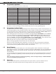
0 0 N N 0 0 TGL MNT 0 0 0 N N N 0 0 N N N N N N N N N N N N N N N N N N N + + + + + N N N N N 1 S S 0 0 0 0 A A A A S S 0 0 T T INT INT INT INT INT INT INT INT INT INT INT N N N N N N N N N N N 0 1 to 8 0 EXT Y Output * or 0 or or Wireless Zone Type Defaults Assign Retard and Presignal for FI, SV, A1, A2, and PN only. Area - For an Area system or a Home/Sleep/Away with Guest system this is 1 to 8.
Appendix 21.12 Common Keypad Messages There are several common keypad messages that the keypad displays to inform the technician and end‑user. The common messages are described below. Possible solutions are also provided. Message Meaning Possible Solutions INVALID AREA The user has attempted a door access for an area they are not assigned. Change the user access areas if access to the area is needed. If access is not needed, the user cannot enter the area.
Appendix 21.
Revisions Revisions to This Document This section explains the changes made to this document during this revision. It lists the date and identifies the change(s) made, the related section number and section heading, and a summary of the change. Guide Version Section Number and Heading Quick Explanation of Changes 1.17 3.5 Communications Type Added 464-263C and 464-263H reference 3.18 Added 464-263C reference 21.2 Removed 463G, added 464-263C AND 464-263H reference 1.16 1.7 Keypads Added 7800 reference 1.
800 - 641 - 4282 Compatible with Devices listed for ANSI/UL 268 Smoke-Automatic Fire Detectors ANSI/UL 346 Waterflow Indicators for Fire Protective Signaling Systems ANSI/UL 636 Intrusion oldup Alarm Units and Systems Accessory H UL Bank, Safe, and Vault • fire • Access • Networks www.dmp.com 2500 North Partnership Boulevard Designed, Engineered and Assembled in U.S.A.