
User's Manual
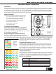
Table Of Contents
INSTALLATION GUIDE
1140 Series Keyfob Transmitters
Description
The 1140 Series offer a Four-Button, Two-Button, or One-Button Keyfob transmitter that is portable, water resistant,
and designed to be clipped to a keychain or lanyard. The 1140 Series keyfobs provide operation within a maximum
of 200 feet of the receiver location. The 1140 Series keyfob LED provides visual acknowledgement when a button
is pressed and responds to each separate operation with specic color-coded LED displays. The 1140 Series keyfobs
operate using the supplied 3.0V universal Lithium coin cell battery.
What is Included
The 1140 Series Keyfob includes the following items:
• One 1145 Four-Button Keyfob Transmitter OR
One 1146 Two-Button Keyfob Transmitter OR
One 1147 One-Button Keyfob Transmitter
• One 3V Lithium CR2032 coin cell battery
• Peel-off Button ID Labels
• LED operation pocket card
• Serial number label
Transmitter Serial Number
For your convenience, an additional pre-printed serial
number label is included. Prior to installing the device,
record the serial number or place the pre-printed serial
number label on the panel programming sheet. This number
is required during programming.
Programming the Keyfob in the Panel
Refer to the XRSuper6/XR20/XR40 Programming Guide
(LT-0305) as needed. Program and assign an address to the
1140 Series Keyfob in Wireless Devices during panel programming. As soon as the 1140 Series keyfob is programmed,
the default button operation is activated. See Figure 1. Should the default
button operation need to be changed, all buttons can be reprogrammed to
operate as needed.
Preparing the Keyfob for Use
Attach the keyfob transmitter to any keyring or lanyard. Select the peel-off
labels that display the programming for each button and place them onto the
corresponding keyfob buttons for quick reference. See Figure 2. For easier
label installation use a small at head screwdriver or X-acto knife to select the
label and apply it to the proper button location as shown in Figure 1. Button
labels can be changed if programming is changed.
LED Communication
When any button is pressed, the LED ashes Green one time for one-half second
to conrm the button press. When the top and bottom buttons are pressed at
the same time, the panel acknowledges with different LED displays to indicate
panel status. The table below describes the LED operation and what the
different color ashes mean.
LED Display What it Means
Green, Green Disarmed and ready to arm.
Green, Yellow Disarmed and trouble.
Red, Red All system armed.
Red, Yellow Armed (Perimeter/Home or Sleep).
Yellow, Yellow System trouble, no acknowledgement, or out of range.
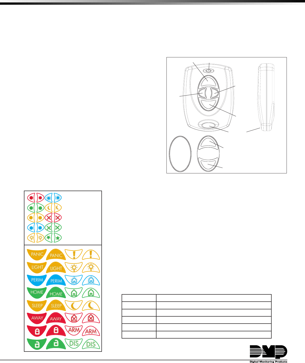
Figure 1: 1140 Series KeyfobTransmitters
Connect
Ke
yring or
Lanya
rd Here
LED
Front View
Side View
Arm
(Home)
Left
Button
Arm (Away)
Top Button
Panic
Righ
t
Button
Disarm
Bottom Button
Ke
yfob
Fron
t
Ke
yfob
Back
Slot Location
Button Callouts
Identify Default
Progr
amming
1146
2-Button
Layout
1147
1-Button
Layout
Arm (Away)
Top Button
Disarm
Bottom Button
1145 4-Button Layout
Figure 2: Button Labels
Optional
Small or
Large
Labels are
available.