
User's Manual
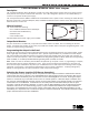


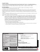
Table Of Contents
- Description
- What is Included
- Output Serial Number
- Programming the Output in the Panel
- Selecting the Proper Location (LED Survey Operation)
- 1118 LED Output Operation
- Installing the 1118 Output
- Powering the 1118 Output
- Battery Power
- Battery Life Expectancy
- Optional External DC Plug-in Power Supply
- Optional External 12 VDC Power Supply
- Output Testing
- FCC Information
- Specifications
- Accessories
- Compatibility
- Patents
- Listings and Approvals

Digital Monitoring Products 1118 Installation Guide
2
1118 Installation Guide Digital Monitoring Products
3
1118 LED Output Operation
When a Panic Alarm is sent, the LED is on steady for ve (5) minutes and then turns off. When a Panic Test is sent to
the 1118 from the 1100 Series Receiver, the LED ashes quickly for ve (5) minutes and then turns off.
Installing the 1118 Output
Mount the 1118 on a at surface such as a wall or single-gang box. When using plug-in power supply operation,
mount the 1118 near a wall outlet. See Figure 2 for mounting hole locations.
Red LED
(Survey)
Tamper
Switch
Red Remote
IndicatorLight
Mounting Holes
+
3.0V
Lithium
Batter
y
—
Internal
Antenna
Location
Power Supply
Adapter Plug
Housing
EXT
BAT
Figure 2: 1118 Output Transmitter PCB and Battery
Powering the 1118 Output
The 1118 output can be powered by:
• CR123A 3.0 VDC battery
• Model 376 plug-in power supply
• 12 VDC Power Supply
Battery Power
Observe polarity when installing the battery. Use only 3.0V Lithium batteries, DMP Model CR123, or the equivalent
battery from a local retail outlet. Do not connect the power supply when operating using battery power.
Note: When setting up a wireless system, it is recommended to program outputs and connect the receiver
before installing batteries in the output transmitters or connecting the optional power supply.
1. Squeeze the cover left and right sides together to remove. See Figure 1.
2. Install a jumper on the two J1 pins next to BAT to enable battery operation.
Note: Battery operation is not enabled if the jumper is on the J1 pins next to EXT.
3. If replacing the battery, remove the old battery and dispose of it properly.
4. Place the 3.0V Lithium battery in the holder and press into place. See Figure 3 for Battery location.
5. Snap the cover back into place.
Caution: Properly dispose of unused batteries. Do not recharge, disassemble, heat above 212°F (100°C),
or incinerate. Risk of re, explosion, and burns.