
User's Manual
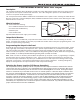


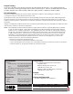
Table Of Contents
- Description
- What is Included
- Output Serial Number
- Programming the Output in the Panel
- Selecting the Proper Location (LED Survey Operation)
- 1118 LED Output Operation
- Installing the 1118 Output
- Powering the 1118 Output
- Battery Power
- Battery Life Expectancy
- Optional External DC Plug-in Power Supply
- Optional External 12 VDC Power Supply
- Output Testing
- FCC Information
- Specifications
- Accessories
- Compatibility
- Patents
- Listings and Approvals

Digital Monitoring Products 1118 Installation Guide
2
1118 Installation Guide Digital Monitoring Products
3
Battery Life Expectancy
Typical battery life expectancy for DMP Model 1118 wireless output transmitter is two to three months when
programmed as a fast response output and three to four years when programmed as a slow response output. Refer
to the XR500 Series Programming Guide (LT-0679), XR100 Series Programming Guide (LT-0896), or the XRSuper6/
XR20/XR40 Programming Guide (LT-0305) as needed. DMP wireless equipment uses two-way communication to
extend battery life.
The following situation can extend battery life expectancy:
• Minimal use of the LED for annunciation.
• Extend output transmitter supervision time in panel programming.
• Program the annunciator as a slow response output in panel programming.
The following situations can reduce battery life expectancy:
• If a receiver is unplugged, too far away, or not installed.
Note: Output transmitters continue to send supervision messages until a receiver returns an
acknowledgement. After an hour the output transmitter only attempts a supervision message every
60 minutes.
• When installed in extreme hot or cold environments.
Optional External DC Plug-in Power Supply
When using the optional plug-in DC power supply, mount the 1118 near
a wall outlet. Do not install a battery when operating using the plug-in
power supply. The plug-in power supply does not charge the battery.
Use the following steps to connect the plug-in power supply:
1. Squeeze the left and right cover sides together to remove. See
Figure 1.
2. Install a jumper on the two J1 pins next to EXT to enable power
supply operation.
Note: Power supply operation is not enabled if the jumper is on
the J1 pins next to BAT.
3. Snap the cover back into place.
4. Plug the power supply barrel connector into the J2 barrel jack at
the side of the 1118 transmitter cover. See Figure 3.
5. Plug the power supply into a 110 Volt AC outlet.
Optional External 12 VDC Power Supply
The 1118 can also be powered from a 12 VDC power supply such as a DMP Model 502-12. Use 22 AWG wire to connect
the barrel connector to the power supply. Purchase the barrel connector at a retail outlet. The power supply does
not charge the battery.
Use the following steps to connect the power supply:
1. Squeeze the left and right cover sides together to remove.
See Figure 1.
2. Install a jumper on the two J1 pins next to EXT to enable
power supply operation.
Note: Power supply operation is not enabled if the jumper is
on the J1 pins next to BAT.
3. Snap the cover back into place.
4. Use 22 AWG wire and connect the positive wire to the pin and
negative wire (GND) to the ring (barrel) on a 5.5 x 2.1 mm
barrel connector. See Figure 4.
5. Connect the other ends of the wires to the J6 DC connector on
the 502-12 power supply PCB. Observe positive and negative
polarity on all connections.
Side View
J2
Po
wer
Supply
Battery Connectors
Barrel Jack
J1
EXT BAT
Jumper
Barrel
Connector
Figure 3: 1118 Side View
Figure 4: Power Supply Connection