
Installation Guide


2 1100XH SERIES WIRELESS RECEIVER | DIGITAL MONITORING PRODUCTS
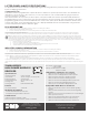
Figure 3: Wiring The 1100XH to the Panel
ADDITIONAL INFORMATION
Wiring Specifications for X-Bus
1. DMP recommends using 18 or 22-gauge unshielded wire for all keypad and LX-Bus circuits. Do Not use twisted pair
or shielded wire for LX-Bus and Keypad Bus data circuits. To maintain auxiliary power integrity when using 22-gauge
wire do not exceed 500 feet. When using 18-gauge wire do not exceed 1,000 feet. Install an additional power supply
to increase the wire length or add devices.
2. Maximum distance for any one circuit (length of wire) is 2,500 feet regardless of the wire gauge. This distance can
be in the form of one long wire run or multiple branches with all wiring totaling no more than 2,500 feet. As wire
distance from the panel increases, DC voltage on the wire decreases.
3. Maximum number of devices per 2,500 feet circuit is 40.
4. Maximum voltage drop between the panel (or auxiliary power supply) and any device is 2.0VDC. If the voltage at
any device is less than the required level, add an auxiliary power supply at the end of the circuit. When voltage is
too low, the devices cannot operate properly. Refer to the panel installation guide and LX-Bus/Keypad Bus Wiring
Application Note (LT-2031).
Programming Zones
Refer to the panel XR150/XR550 Series Programming Guide (LT-1232) for complete wireless programming information.
When any wireless input zone for a particular address is programmed, the 1100XH responds to the panel for this address.
Other devices, such as keypads or hardwired zone expanders, cannot use this address. Zones connected directly to the
panel cannot be wireless. See Table 1 for designated zone numbers.
WIRE THE RECEIVER
The panel immediately recognizes the 1100XH if the panel is programmed with a house code. Do not use
shielded wire between the panel and receiver.
1. Connect the red, yellow, green, and black wires to the PANEL terminal on the 1100XH.
2. Connect the other end of the wires to the XBUS on the panel. See Figure 3.
3. Snap the cover back on to the base.
Note: The receiver can’t operate if it’s connected to the keypad bus
4
Can be extended up to
500 ft from the panel using
22 AWG or 1,000 ft using
18 AWG
XR150/XR550
Series Panel
Battery Start
Power LED
1100XH
Receiver
REC - Receive LED
XMT - Transmit LED
RF RX
RF TX
PANEL RX
PANEL TX
WALL
TAMPER
ENABLE
DISABLE
STAT U S
PWR
PANEL
TAMPER
Table 1: Zone Number Designations
DMP PANEL AVAILABLE ZONES ZONE RANGES
XR150 (1100X Series) 100 500 - 599
XR550 (1100X Series) 500 500 - 999