
User's Manual


Digital Monitoring Products 1105 Installation Guide
2
Mounting the Transmitter and Magnet Assemblies
Forinternalcontactoperation,thetransmitterandmagnetassemblyshouldhavenomorethan1/2"spacebetween
the assembled housings after installation. When mounting on metal (ferrous) surfaces, this distance is slightly less.
For door installations, it is recommended the transmitter be mounted on the door frame and the magnet assembly
be mounted on the door.
Magnet Assembly
Only one magnet assembly is required for internal reed switch operation. Depending on the installation
requirements,eithertheStandardMagnetAssembly(Figure3)ortheCommercialMagnetAssembly(Figure4)canbe
used.
Installing the Transmitter
The following instructions cover installing the transmitter and magnet assembly.
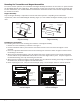
1. Remove the cover and battery if installed. See Figure 1.
2.Holdthetransmitterbaseinplacewiththereedswitchnearesttotheareawherethemagnetistobe
mounted.
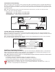
3.Placetwosupplied#4atheadscrewsintothemountingholelocationsasshowninFigure5and6tosecure
the housing to the surface.
4.Whenusingthestandardmagnet,placethemagnetbaseonthesurfacenearesttotheinternalreedswitch
locationandusetheprovided#4atheadscrewstosecurethemagnetbaseinplace.Snapthemagnetinto
the standard housing, then snap the housing onto the base.
5.Whenusingthecommercialmagnet,snapthemagnetintothecommercialhousing,thenusingthesupplied#4
atheadscrews,mountthemagnetinthedesiredlocation.
6. Before replacing the cover, verify the internal tamper spring is on the tamper switch for normal operation.
Housing
Base
Magnet
Magnet
Housing
#4 Flat Head
Screws
Figure 3: Standard
Magnet Assembly
Minimum 1/8”
Mounting
distance
Wall Mount
Screw Holes
Standard Magnet Base
Figure 5: Transmitter and
Standard Magnet
Minimum 1/8”
Mounting
distance
Commercial Magnet
Wall Mount
Screw Holes
Figure 6: Optional
Commercial Magnet
Magnet
Housing
Magnet
#4 Flat Head
Screws
Figure 4: Commercial
Magnet Assembly