
User's Manual
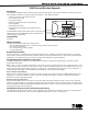
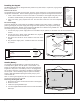


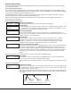


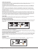

Table Of Contents
- 9000 Series Wireless Keypads
- Description
- What is Included
- Keypad Serial Number
- Programming the Transmitter in the Panel
- Selecting the Proper Location (LED Survey Operation)
- Installing the Keypad
- Standby Battery
- Card Reader
- Panic Key Options
- Internal Speaker Operation
- Backlighting
- Backlit Keyboard and Logo
- End-User Options
- Entering Alpha Characters
- Entering Non-Alphanumeric Characters
- Installer Options Menu
- Additional Programming
- User’s Guide
- Keypad Arming and Disarming
- Keypad Entry Delay
- FCC Information
- Specifications
- Compatibility
- Patents
- Accessories

9000 Series Installation Guide Digital Monitoring Products
3
Battery Replacement
1. Disconnect the battery lead connector from the
keypad J3 battery header.
2. Remove the battery strap from the standby battery.
3. Remove and properly dispose of the used battery.
Caution: Risk of re, explosion, and burns. Do not
disassemble, heat above 212°F (100°C), or incinerate.
Properly dispose of used batteries.
4. Place the new battery on the keypad PCB and replace
the battery strap.
5. Observe polarity and connect the battery lead
connector to the keypad J3 battery header.
Installing Keypad PCB
1. Set the keypad PCB into the bottom snaps
2. Line up the PCB alignment post with the hole in the
keypad PCB.
3. Press the PCB into the top PCB snaps to secure in place.
4. Replace the base.
Battery Supervision
The panel tests the battery once every hour when DC power is present. This test occurs 15 minutes past each hour and
lasts for ve seconds. A load is placed on the battery and if the battery voltage is low, a low battery is detected. If DC
power has failed, a low battery is detected any time the battery voltage falls below 3.7V.
Card Reader
When a proximity credential is presented to the Model 9063 internal reader, a beep tone is heard and the Power and Armed
LEDs blink. This provides both an audible and visual acknowledgement of the credential read.
Panic Key Options
2-Button Panic Keys
All keypads offer Panic key function that allows users to send Panic, Emergency, or Fire reports to the central station.
Enable the Panic key function in the keypad user menu. See Keypad Programming Instructions later in this document.
Install the supplied icon labels below the top row of Select keys as shown in Figure 4.
The user must press and hold the two Select keys for two seconds until a beep from the keypad is heard. At the beep, the
panel sends the following zone alarm reports to the central station:
Panic (left two Select keys)—Zone 19 + Device Address
Emergency—non-medical (center two Select keys)—Zone 29 + Device Address
Fire (right two Select keys)—Zone 39 + Device Address
Internal Speaker Operation
All keypads emit standard tones for key presses, entry delay, and system alerts. The speaker also provides distinct
burglary, re, zone monitor, and prewarn cadences. The keypads provide an alternate prewarn with alarm cadence that
occurs when the status list displays a zone alarm.
Backlighting
Both the logo and keyboard light when a key is pressed or the speaker sounds.
During an alarm condition, all lighted areas turn Red. When all alarm conditions are cleared from the display, the Red
display turns off and the lighted areas return to the user-selected brightness.
Backlit Keyboard and Logo
The backlit keyboard and logo indicate the power and armed status of the panel. Depending on the status, the LED
displays in Red or Green as listed in the table.
Color and Activity Operation
Green Steady Panel Disarmed, AC Power OK, Battery OK
Green Blinking Panel Disarmed, AC Power OK, Battery Fault
No Light Panel Disarmed, AC Power Fault, Battery OK
Red Steady Panel Armed, AC Power OK, Battery OK
Red/Green Alternate Panel Armed, AC Power OK, Battery Fault
Red Blinking Panel Armed, AC Power Fault, Battery OK
Standby battery
connector
Standby
battery
strap
Figure 5: Battery Replacement