
User's Manual


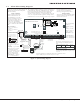
Table Of Contents
- Panel Specifications
- Introduction
- System Components
- Installation
- Primary Power Supply
- Secondary Power Supply
- Bell Output
- Keypad Data Bus
- Smoke and Glassbreak Detector Output
- Burglary Zones
- Powered Zone for 2-Wire Smoke Detectors
- Annunciator Outputs
- Telephone RJ Connector
- Ethernet Connector J1
- Reset Header J16
- Flash Load Jumper J18
- Cellular Connections
- On-Board 1100 Series Wireless Antenna Connection
- Wireless Keypads
- Listed Compliance Specifications
- Household Burglar-Alarm System Units ANSI/UL 1023
- Digital Burglar Alarm Communicator System Units ANSI/UL 1635
- Central Station Burglar Alarm Units ANSI/UL 1610
- Household Fire Warning System ANSI/UL 985 NFPA 72 Specifications
- California State Fire Marshal Specifications
- False Alarm Reduction Programmable Options ANSI/SIA CP-01-2010
- Troubleshooting
- Wiring Diagrams
- Revisions to This Document

XT30/XT50 Installation Guide Digital Monitoring Products
i
Table of ConTenTs
Panel Specications
1.1 Power Supply .........................................1
1.2 Communication .......................................1
1.3 Panel Zones ............................................1
1.4 Keypads/Expansion .................................1
1.5 Number of Zones ....................................1
1.6 Outputs ..................................................1
1.7 EnclosureSpecications ..........................1
Introduction
2.1 SystemCongurations .............................2
2.2 Caution Notes .........................................2
2.3 Compliance Instructions ..........................2
System Components
3.1 WiringDiagram .......................................2
3.2 LightningProtection ................................2
3.3 AccessoryDevices ...................................2
3.4 XT30/XT50WiringDiagram .....................5
Installation
4.1 MountingtheEnclosure ...........................6
4.2 MountingKeypads ..................................7
4.3 InstallationSpecications ........................7
Primary Power Supply
5.1 AC terminals 1 and 2 ...............................7
5.2 Transformer Types ..................................7
5.3 PowerLED .............................................7
Secondary Power Supply
6.1 Battery Terminals 3 and 4 ........................8
6.2 EarthGround ..........................................8
6.3 Replacement Period ................................8
6.4 Discharge/Recharge ................................8
6.5 BatterySupervision .................................8
6.6 XT30/XT50 Power Requirements ..............8
6.7 XT30/XT50 Standby Battery Calculations ..9
Bell Output
7.1 Terminals 5 and 6 .................................10
Keypad Data Bus
8.1 Description ...........................................10
8.2 Terminal7-RED...................................10
8.3 Terminal 8 - YELLOW ............................10
8.4 Terminal9-GREEN...............................10
8.5 Terminal 10 - BLACK .............................10
8.6 KeypadBusLEDs ..................................10
8.7 ProgrammingConnection ......................10
8.8 KeypadAddressing ................................10
8.9 OvercurrentOVCLED ............................11
Smoke and Glassbreak Detector Output
9.1 Terminal 11 ..........................................11
Burglary Zones
10.1 Description ...........................................11
10.2 Operational Parameters .........................11
10.3 Zone Response Time .............................12
10.4 KeyswitchArmingZone .........................12