
User's Manual


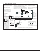
Table Of Contents
- Panel Specifications
- Introduction
- System Components
- Installation
- Primary Power Supply
- Secondary Power Supply
- Bell Output
- Keypad Data Bus
- Smoke and Glassbreak Detector Output
- Burglary Zones
- Powered Zone for 2-Wire Smoke Detectors
- Annunciator Outputs
- Telephone RJ Connector
- Ethernet Connector J1
- Reset Header J16
- Flash Load Jumper J18
- Cellular Connections
- On-Board 1100 Series Wireless Antenna Connection
- Wireless Keypads
- Listed Compliance Specifications
- Household Burglar-Alarm System Units ANSI/UL 1023
- Digital Burglar Alarm Communicator System Units ANSI/UL 1635
- Central Station Burglar Alarm Units ANSI/UL 1610
- Household Fire Warning System ANSI/UL 985 NFPA 72 Specifications
- California State Fire Marshal Specifications
- False Alarm Reduction Programmable Options ANSI/SIA CP-01-2010
- Troubleshooting
- Wiring Diagrams
- Revisions to This Document

Digital Monitoring Products XT30/XT50 Installation Guide
2
IntroductIon
Introduction
2.1 System Congurations
The panel can be programmed to operate as any of the following system types:
• All/Perimetersystemthatprovidesoneperimeterareaandoneinteriorarea
• Home/Sleep/Awaysystemthatprovidesoneperimeter,oneinterior,andonebedroomarea.The
bedroom area provides for any protection devices the user wants disarmed during their sleeping hours
and armed in the Away mode.
• Sixareasystemthatprovidesareasofprotectionthatcanbeindependentlyarmedordisarmed.
2.2 Caution Notes
Throughoutthisguideyouwillseecautionnotescontaininginformationyouneedtoknowwheninstalling
thepanel.Thesecautionsareindicatedwithayieldsign.Wheneveryouseeacautionnote,makesureyou
completely read and understand its information. Failing to follow the caution note can cause damage to the
equipment or improper operation of one or more components in the system. See the example shown below.
Always ground the panel before applying power to any devices: The panel must be properly grounded
before connecting any devices or applying power to the panel. Proper grounding protects against
ElectrostaticDischarge(ESD)thatcandamagesystemcomponents.
Remove All Power From the Panel! Remove all AC and Battery power from the panel before installing or
connecting any modules, cards, or wires to the panel.
2.3 Compliance Instructions
ForapplicationsthatmustconformtoalocalauthoritiesinstallationstandardoraNationalRecognizedTesting
Laboratorycerticatedsystem,pleaseseetheListedComplianceSpecicationssectionneartheendofthis
guide for additional instructions.
System Components
3.1 Wiring Diagram
The system wiring diagram in Figure 1 shows some of the accessory devices for use in various applications. A
description of each module follows.
3.2 Lightning Protection
MetalOxideVaristorsandTransientVoltageSuppressorshelpprotectagainstvoltagesurgesoninputand
output circuits. This transient protection provides additional resistance to electrical surges such as lighting.
AdditionalsurgeprotectionisavailablebyinstallingtheDMP370or370RJLightningSuppressors.