
User's Manual


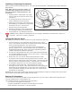
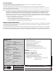
Table Of Contents
- Description
- Compatibility
- What is Included
- Transmitter Serial Number
- Programming the Transmitter in the Panel
- Selecting the Proper Location (LED Survey Operation)
- Installing the Detector
- Installing or Replacing the Batteries
- Testing the Detector
- Battery Life Expectancy
- FCC Information
- Industry Canada Information
- Specifications
- Compatibility
- Patents
- Listings and Approvals

1183 Detector Installation Guide Digital Monitoring Products
3
Installing or Replacing the Batteries
Observe polarity when installing the battery. Use only 3.0V lithium batteries, DMP Model CR123-FIRE or Panasonic
Model CR123A.
Note: When setting up a wireless system, it is
recommended to program zones and connect
the receiver before installing batteries in the
transmitters.
1. Slide the battery compartment cover away
from the detector to unsnap it and lift it off.
See Figure 4.
2. If replacing the battery, remove the old
battery and dispose of them properly.
3. Observing correct polarity, insert the new 3V
lithium battery into the battery compartment
and replace the cover. Use only new
batteries when replacing old ones.
4. Reattach the detector to the mounting base.
See Attaching and Removing the Detector.
5. Test the detector. See Testing the Detector.
Caution: Properly dispose of used batteries. Do not recharge, disassemble, heat above 212°F (100°C), or
incinerate. Risk of re, explosion, and burns.
Testing the Detector Alarm
The 1183 Series detectors provide a test button to verify the detector operation.
1. To test the detector, rst enable Walk Test operation on the control
panel. If the system is monitored, the system sends a System Test Begin
report (System message S66) to the central station.
To conduct the Walk Test, reset the control panel by momentarily
placing a jumper on J16. From the keypad, enter the code 8144. The
keypad displays WALK TEST. Refer to the panel programming guide for
complete information on Walk Test operation.
2. For the XTL or XT30/XT50 Series panels, select STD (Standard Walk Test).
For the XR100/XR500 Series panels, select FI (Fire zones). A sensor reset
occurs after each detector tested.
3. Remove the cover over the test button opening and insert a small
screwdriver in the test button opening and press the test button. The
detector sends an alarm signal to the control panel. Verify that the walk
test trip counter increments to indicate a successful test. Once testing
is completed, replace the cover over the test button opening.
4. Select END to stop the Walk Test. When the Walk Test ends or a
20-minute time-out expires, a nal Sensor Reset occurs. The System Test
End message (System message S67) is sent to the central station along
with verify and fail messages for each zone under test. Faulted zones
then display on the keypad.
Important: The control panel alarm and all auxiliary functions should be veried for a complete test of the system.
See the panel programming guide for additional information.
Battery Life Expectancy
Typical battery life expectancy for DMP wireless heat detectors is at least 2 years. DMP wireless equipment uses
two-way communication to extend battery life.
The following situations can reduce battery life expectancy:
• If a receiver is unplugged or not installed.
• Frequent transmissions, such as how often the detector is tested.
• When installed in extreme hot or cold environments.
Figure 4: Battery Compartment
Battery
Compartment
Battery Cover
Battery
Detector Cap
Mounting Base
Test Button
Alignment
Notch
Tamper Post
Detector Cover
Battery Compartment
Heat
Collector
Fin
Figure 5: Test Button