Installation Guide XR150/XR350/XR550 Series Control Panel
MODEL XR150/XR350/XR550 SERIES INSTALLATION GUIDE FCC NOTICE This equipment generates and uses radio frequency energy and, if not installed and used properly in strict accordance with the manufacturer’s instructions, may cause interference with radio and television reception.
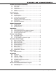
Table of Contents Product Specifications Summary 1.1 1.3 1.4 1.5 1.6 1.7 Power Supply..........................................................................1 Panel Zones............................................................................1 Keypad Bus.............................................................................1 LX500-LX900 Bus™.................................................................1 Outputs..................................................................................
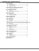
Table of Contents Protection Zones 10.1 10.2 10.3 10.4 Terminals 13–24....................................................................14 Operational Parameters..........................................................14 Zone Response Time..............................................................14 Keyswitch Arming Zone..........................................................14 Powered Zones for 2-Wire Smoke Detectors 11.1 Terminals 25–26 and 27–28.................................................
Introduction Product Specifications Summary 1.1 Power Supply Transformer Input: Model 327, plug-in — Primary input: 120 Vac, 60 Hz, Secondary output: 16.5 Vac 50 VA Model 322/323, wire-in — Primary input: 120 Vac, 60 Hz, Secondary output: 16 Vac 56 VA Model 324/324P, wire-in — Primary input: 120 Vac, 60 Hz, Secondary output: 16 Vac 100 VA Standby Battery: 12 Vdc, 1.0 Amps Max. charging current Models 364, 365, 366, 368, or 369 Replace every 3 to 5 years Auxiliary *: 12 Vdc output at 1.
Panel specifications 2.1 Description 2.2 Zone Expansion Panel Features The DMP XR150/XR350/XR550 Series system is made up of an alarm panel with a built-in communicator, an enclosure, battery, one transformer, and keypads. Each panel is a versatile 12 Vdc, combined access control, burglary, and fire communicator panel with battery backup. The panels provide eight on-board burglary zones and two on-board 12 Vdc Class B powered zones.
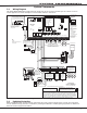
System Components 3.1 System Components Wiring Diagram The XR150/XR350/XR550 Series diagram below shows some of the accessory modules you can connect for use in various applications. A brief description of each module follows in section 3.3. s AC Wiring must be in conduit and exit out the left side of the enclosure.
System components 3.3 Accessory Devices Cellular Communicator Cards 263C CDMA Cellular Communicator Allows you to connect the XR150/XR350/XR550 Series to any compatible CDMA/SMS network. Allows you to connect the XR150/XR350/XR550 Series to any compatible HSPA/SMS network.
system components DMP Two-Way Wireless Devices (continued) 1142BC Two-button Hold-up Belt Clip Transmitter 1142 Two-button Hold-up Transmitter 1145-4 (Four-Button) 1145-2 (Two-Button) 1145-1 (One‑Button) 1161 Residential Smoke Detector 1162 Residential Smoke/Heat Detector 1183-135F Heat Detector 1183-135R Heat Detector 1184 Carbon Monoxide Detector Provides two-button hold-up operation with a belt clip. Provides permanently mounted under-the-counter two-button hold-up operation.
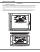
Installation Installation 4.1 Mounting the Enclosure The metal enclosure for the XR150/XR350/XR550 Series must be mounted in a secure, dry place to protect the panel from damage due to tampering or the elements. It is not necessary to remove the panel PCB when installing the enclosure. Figure 2 shows the mounting hole locations for the Model 350/350A Enclosures. Figure 3 shows the Model 341 Kiosk Enclosure. Figure 4 shows the Model 352X panel cabinet and 352S shelf cabinet for multiple batteries.
Installation 56 VA Transformer Mounting Plate XR550 Panel XR550 Panel J6 K Mounting for one (1) Zone Expansion Module. Battery Shelf Figure 4: XR550 Series in Model 352X Enclosure and Separate 352S Enclosure with Shelves 4.2 Mounting Keypads and Zone Expansion Modules DMP LCD keypads have removable covers that allow you to easily mount the keypad to a wall or other flat surface using the screw holes on each corner of the base.
Installation 4.3 Connecting LX-Bus and Keypad Bus Devices 4.4 Wireless Keypad Association Connections for LX-Bus and Keypads are provided through the J8 (PROG), J14 (LX500), J9 (LX600), J15 (LX700), J17 (LX800), J19 (LX900), and J13 (XBUS) 4-pin headers. Several factors determine the DMP LX-Bus™ and keypad bus performance characteristics: the wire length and gauge used, the number of devices connected, and the voltage at each device.
Installation Secondary Power Supply 6.1 Battery Terminals 3 and 4 Battery Start Connect the black battery lead to the negative XR550 Panel battery terminal. The negative terminal connects to AC AC +B –B BELL GND the enclosure ground internally through the XR150/ Battery XR350/XR550 Series circuit board. Connect the 1 2 3 4 5 6 To AC 318 Battery red battery lead to the battery positive terminal. Harness Red Panel Red and Observe polarity when connecting the battery.
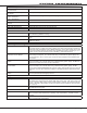
Installation 6.8 Power Requirements During AC power failure, the XR150/XR350/XR550 Series panel and all connected auxiliary devices draw their power from the battery. All devices must be taken into consideration when calculating the battery standby capacity. The following table lists the XR150/XR350/XR550 Series panel power requirements.
Installation Standby Battery Power Calculations Standby Current Alarm Current 736P POPIT Interface Module Radionics Popex, POPITs, OctoPOPITs Qty _______ Qty _______ x 25mA ______ x ___mA ______ Qty _______ Qty _______ x x 25mA ______ ___mA ______ 738A Ademco Wireless Interface Module Qty _______ x 75mA ______ Qty _______ x 75mA ______ 738Z Z-Wave Interface Module Qty _______ x 35mA ______ Qty _______ x 35mA ______ 710 Bus Splitter/Repeater Module Qty _______ x 32mA ______ Qty ___
Installation 6.9 Standby Battery Selection To choose the type and number of batteries needed for 24, 60, or 72 hours of standby power based on the Amp Hours Required calculation from section 6.8 XR150/XR350/XR550 Series Power Requirements, perform the following: 1. Select the desired standby hours required from the table below: 24, 60, or 72 hours 2. Select the desired battery size: Model 368 (12 Vdc 5.
Installation Bell Output 7.1 Terminals 5 and 6 Terminal 5 supplies positive 12 Vdc to power alarm bells or horns. This output can be steady, pulsed, or temporal depending upon the Bell Action specified in Bell Options. Terminal 6 is the ground reference for the bell circuit. This supervised output detects 1k Ohms or less as normal. The indicating appliance can supply this resistance.
Installation Smoke and Glassbreak Detector Output 9.1 Terminals 11 and 12 9.2 Current Rating Terminal 11 supplies positive 12 Vdc Regulated to power 4-wire smoke detectors and other powered devices. This output can be turned off by the user for 5 seconds using the Sensor Reset User Menu option to allow latched devices to reset. Terminal 12 is the ground reference for terminal 11. The Output current from terminal 11 is shared with terminals 7, 25, 27, and LX500-LX900.
Installation Powered Zones for 2-Wire Smoke Detectors 11.1 Terminals 25–26 and 27–28 Panel terminals 25 through 28 provide two resettable Class B, Style A, 2-wire powered zones. For programming purposes the zone numbers are 9 and 10. Note: The maximum wire length for either zone 9 or zone 10 is 3000 feet using 18 AWG or 1000 feet using 22 AWG. The maximum voltage is 13.8 Vdc and the maximum normal standby current is 1.25mA DC. The maximum line impedance is 100 Ohms.
Installation Annunciator Outputs 13.1 Description 13.2 Model 300 Harness Wiring The four programmable annunciator outputs can be programmed to indicate the activity of the panel zones or conditions occurring on the system. Annunciator outputs do not provide a voltage but instead switch-to-ground a voltage from another source. The outputs can respond to any of the conditions listed in the Description section for Dry Contact Relays. Maximum voltage is 30 Vdc @ 50mA.
Installation J1 Ethernet Connector (Panels with Network/Encryption only) 16.1 Description The J1 Ethernet Connector is available on the XR150/XR350/XR550 with network or encryption to connect directly to an Ethernet network using a standard patch cable. The Ethernet Connector supports 100MB/s full duplex operation and the maximum impedance is 100 Ohms. Ethernet LEDs The two LEDs, located on the top edge of the J1 Ethernet Connector, indicate network connection.
Installation J3 Telephone RJ Connector 17.1 Description Connect the panel to the public telephone network by installing a DMP 356 RJ Cable between the panel J3 connector and the RJ31X or RJ38X phone block. The maximum impedance is 100 Ohms. CAUTION - To reduce the risk of fire, use only No. 26 AWG or larger telecommunication line cord, such as DMP Model 356 Series Phone Cords. 17.2 J10 893A or 277 Connector Connect an 893A Dual Phone Line Module or Model 277 Trouble Sounder to J10 on the panel.
Installation If the XR150/XR350/XR550 Series causes harm to the telephone network, the telephone company will notify you in advance that temporary discontinuance of service may be required. But if advance notice isn’t practical, the telephone company will notify the customer as soon as possible. Also, you will be advised of your right to file a complaint with the FCC if you believe it is necessary.
Installation Cellular Modules 19.1 J24 Header The J24 header is located to the right of the J7 Expansion Module on the right side of the circuit board and is used to connect the DMP Model 263C CDMA or 263H HSPA+ Cellular Communicators. This provides a fully supervised alarm communication path for the XR150/XR350/XR550 panel. Refer to the 263C (LT-1264), or 263H (LT-1270) Installation Sheet for complete information. 19.2 Module Installation 1.
XR150/XR350/XR550 Series Installation Guide Digital Monitoring Products 21
800 - 641 - 4282 The XR550 with encryption uses AES encryption and any export beyond the United States must be in accordance with Export Administration Regulations. Intrusion • fire • Access • Networks www.dmp.com 2500 North Partnership Boulevard Designed, Engineered and Assembled in U.S.A.