
Installation guide

Digital Monitoring Products XR150/XR350/XR550 Series Installation Guide
16
InstallatIon
Annunciator Outputs
13.1 Description
The four programmable annunciator outputs can be programmed to indicate the activity of the panel zones or
conditions occurring on the system. Annunciator outputs do not provide a voltage but instead switch-to-ground a
voltage from another source. The outputs can respond to any of the conditions listed in the Description section for
Dry Contact Relays. Maximum voltage is 30 Vdc @ 50mA.
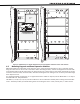
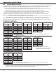
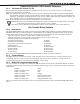
13.2 Model 300 Harness Wiring
Access the open collector outputs by installing DMP 300 Harness on the 4-pin header labeled J11. The output
locations are shown below. For listed applications, devices connected to the outputs must be located within the
same room as the panel.
Output Color Wire Output Color Wire
3 Red 1 5 Green 3
4 Yellow 2 6 Black 4
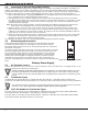
13.3 Model 860 Relay Module
Connect a Model 860 Relay Module to the J11 header on the XR150/XR350/XR550 Series panel to provide relays for
outputs 3-6.
Use these relays for electrical isolation between the alarm panel and other systems or for switching voltage to
control various functions. Power is supplied to the relay coils from a single wire connected to the panel auxiliary
power terminal 7. The module includes one relay and provides three additional sockets for expansion of up to four
relays. Mount the 860 inside the panel enclosure using the 3-hole pattern and plastic standoffs. Refer to the 860
Module Install Sheet (LT-0484) as needed.
Relay Contact Rating: 1 Amp at 30 Vdc (allows .35 power factor)
Wireless Bus Expansion
14.1 Description
The J13 Wireless Bus (XBUS) header provides connection for the 1100X or 1100XH Wireless Receiver. The XBUS
provides up to 500 wireless zones numbered 500-999. Refer to the 1100X Wireless Receiver Install Guide (LT-0708) or
the 1100XH Wireless Receiver
Install Guide (LT-0970) for complete information.
• XR550 provides up to 500 zones
• XR350 provides up to 300 zones
• XR150 provides up to 100 zones
14.2 Wireless Bus LEDs
The two LEDs, located above the XBus header, indicate data transmission and receipt. The left LED ashes green to
indicate the panel is transmitting data. The right LED ashes yellow to indicate the panel is receiving data.
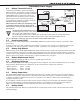
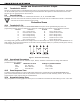
LX-Bus Expansion
15.1 LX-Bus Headers
There are ve LX-Bus headers near the bottom of the
XR150/XR350/XR550 panel:
• LX500 (J14), provides zones 500-599 (all panels).
• LX600 (J9), provides zones 600-699 (XR350 and XR550 only).
• LX700 (J15 ), provides zones 700-799 (XR350 and XR550 only).
• LX800 (J17 ), provides zones 800-899 (XR550 only).
• LX900 (J19 ), provides zones 900-999 (XR550 only).
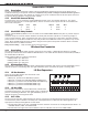
15.2 LX-Bus LEDs
The two LEDs, located above each LX-Bus header, indicate data
transmission and receipt. The left LED ashes green to indicate the
panel is transmitting LX-Bus data. The right LED ashes yellow to
indicate the panel is receiving LX-Bus data.
15.3 OVC LEDs
The Overcurrent LED (OVC) lights Red when the devices connected to the Keypad Bus and LX-Bus(es) draw more
current than the panel is rated for. The LED(s) turn a steady Red when lit. When the OVC LED(s) light Red, the
appropriate LX-Bus(es) and Keypad bus are shut down.
• The OVC LED located to the left of the 893A connector indicates overcurrent for the Keypad Bus (Terminals 7-10
and PROG header), XBUS, and LX500-LX700.
• The OVC LED to the right of the J24 Cell Module connector indicates overcurrent for LX800-LX900.
Figure 9: LX-Bus Headers and LEDs