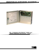
INSTALLATION GUIDE XR6 COMMAND PROCESSOR™ PANEL and XR10 COMMAND PROCESSOR™ PANEL
MODEL XR6/XR10 COMMAND PROCESSOR INSTALLATION GUIDE FCC NOTICE This equipment generates and uses radio frequency energy and, if not installed and used properly in strict accordance with the manufacturer's instructions, may cause interference with radio and television reception.
Section TABLE OF CONTENTS Page Panel Specifications ............................................................................... 1 1.1 Power Supply ................................................................. 1 1.2 Communication .............................................................. 1 1.3 Panel Zones ................................................................... 1 1.4 Keypads ........................................................................ 1 1.5 Outputs ......................
Section TABLE OF CONTENTS Page Powered Zone for 2-Wire Smoke Detectors ...................................... 11 11.1 Terminals 25 and 26 ....................................................... 11 Annunciator Outputs ............................................................................ 12 12.1 Description ................................................................... 12 12.2 Harness Wiring .............................................................. 12 12.3 Model 860 Relay Module ..........
Section TABLE OF CONTENTS Page UNIVERSAL UL and NFPA FIRE ALARM SPECIFICATIONS ................ 17 20.1 Introduction .................................................................. 17 20.2 Wiring .......................................................................... 17 20.3 Police station phone number ............................................ 17 20.4 System maintenance ....................................................... 17 20.5 Audible alarm .................................................
This page left intentionally blank.
INTRODUCTION Panel Specifications 1.1 Power Supply Transformer Input: 16.5 VAC 40VA (Models 320 wire-in or 321 plug-in) 16.5 VAC 20VA (Model 324 plug-in) Standby Battery: 12 VDC 7.0Ah (40VA transformer charges up to 2 batteries) Auxiliary Output: 12 VDC at 500mA Bell Output: 12 VDC at 1.5 Amps with 40VA transformer, 600mA with 20VA transformer Smoke Detector Output: 12 VDC at 100mA All circuits inherent power limited 1.
INTRODUCTION Introduction 2.1 Description The DMP XR6/XR10 Command Processor® panels are powerful 12 VDC burglary and fire communicator panels with battery backup. The XR10 provide nine on-board burglary zones and one on-board 12 VDC Class B powered fire zone. The XR6 provides five burglary and one fire zone. The fire zone has a reset capability to provide for 2-wire smoke detectors, relays, or other latching devices.
INTRODUCTION System Components 3.1 Description The DMP system is made up of an alarm panel with built in communicator, an enclosure, a 16.5 VAC transformer, and a 12 VDC 7.0 Ah battery. You can add Security Command keypads to the system and can also connect auxiliary devices to the panel's open collector outputs to expand the basic system. Combined current requirements of additional modules may require an auxiliary power supply.
INTRODUCTION 3.5 XR6/XR10 Wiring Diagram The Class 2, Class 3, and power-limited fire alarm circuits are installed using CL3, CL3R, or CL3P, or substitute cable permitted by the National Electric code, ANSI/ NFPA 70, and the Class 2, Class 3, and power-limited fire alarm circuit conductors extending beyond the cable jacket are separated a minimum of 1/4 in. or by nonconductive tubing or by a nonconductive barrier.
INSTALLATION Installation 4.1 Mounting the Enclosure The metal enclosure must be mounted in a secure, dry place to protect the panel from damage due to tampering or the elements. It is not necessary to remove the PCB when installing the enclosure. The PCB may be installed in the standard 340 enclosure, or the optional 349 enclosure, or the optional 350A Grade A enclosure.
INSTALLATION 4.2 Mounting Keypads Security Command keypads have removable covers that allow you to easily mount the base to a wall or other flat surface using the screw holes provided on each corner. For mounting keypads on solid walls, or for applications where conduit is required, use a DMP 695, 696, 775, or 776 keypad conduit backbox. 4.3 Wiring Keypads The keypad data bus consists of a 4-wire cable that provides 12 VDC power, data in, data out, and a panel common.
INSTALLATION Secondary Power Supply 6.1 Battery Terminals 3 and 4 Connect the black battery lead to terminal 4 on the panel and to the negative terminal of the battery. The negative terminal connects to the enclosure ground internally through the panel circuit board. Connect the red battery lead to terminal 3 on the panel and to the positive terminal of the battery. Observe polarity when connecting the battery. The panel can charge up to two batteries.
INSTALLATION 6.7 XR6/XR10 Standby Battery Calculations Standby Current Command Processor Panel Active Zones 1-9 50mA ______ mA 1.6mA ______ mA Qty _____ x Qty _____ x .1mA ______ mA Qty _____ x *2mA ______ mA 4mA ______ mA Bell Output 30mA ______ mA .1mA ______ mA 1500mA max.
INSTALLATION Bell Output 7.1 Terminals 5 and 6 Nominal 12 VDC is supplied by terminal 5 on the panel to power alarm bells or horns. The output is rated for a maximum of 1.5 Amps with a 40VA transformer and 600mA with a 20VA transformer. This output can be steady, pulsed, or Temporal Code 3 depending upon the Bell Action specified in Output Options programming. Terminal 6 is the ground reference for the bell circuit. Keypad Data Bus 8.
INSTALLATION Burglary Zones 10.1 Description The XR10 terminals 12 to 24 are the nine burglary zones. For programming purposes, the zone numbers are 1 to 9. The zone configurations on terminals 12 to 24 are described below. The XR6 terminals 12 to 18 are the five burglary zones with terminal 16 providing the ground for zone 5.
INSTALLATION Powered Zone for 2-Wire Smoke Detectors 11.1 Terminals 25 and 26 A resettable 2-wire Class B powered zone is provided on terminals 25 (positive) and 26 (negative) of the panel. For programming purposes, the zone number is 10 on the XR10 and zone 6 on the XR6. The zone uses a Model 309, 3.3k Ohm EOL resistor (provided with the panel) and has an operating range of 8.8 to 14.2 VDC. Power is dropped from zone 10 any time a Sensor Reset is performed on the panel.
INSTALLATION Annunciator Outputs 12.1 Description The four annunciator outputs can be programmed to indicate the activity of the panel's zones or conditions occurring on the system. Annunciator outputs do not provide a voltage but instead switch to ground voltage from another source.
INSTALLATION 13.2 FCC Registration The panel complies with FCC part 68 and is registered with the FCC. Registration number: CCKUSA - 18660 - AL - R Ringer Equivalence: 1.1B 13.3 Notification Registered terminal equipment must not be repaired by the user. In case of trouble, the device must be immediately unplugged from the telephone jack. The factory warranty provides for repairs. Registered terminal equipment may not be used on party lines or in connection with coin telephones.
COMPLIANCE UNIVERSAL UL BURGLARY SPECIFICATIONS 15.1 Introduction The programming and installation specifications contained in this section must be completed when installing the XR6/ XR10 in accordance with any of the UL burglary standards. Additional specifications may be required by a particular standard. 15.2 Wiring All wiring must be in accordance with NEC, ANSI/NFPA 70, UL 681, and UL 611 for all burglary installations. 15.
COMPLIANCE UL 1610 and 1076 SPECIFICATIONS Central-Station and Proprietary Burglar-Alarm Units 17.1 Opening/Closing reports The Opening/Closing Reports option must be programmed as YES. See the XR6/XR10 Programming Guide (LT-0230). 17.2 Automatic bell test This option must be programmed as YES. See the XR6/XR10 Programming Guide (LT-0230). 17.3 Proprietary dialer The Model XR6/XR10 provides Grade A proprietary service when configured as a digital dialer.
COMPLIANCE UL 365 and 609 SPECIFICATIONS Police Station Connected and Local Burglar Alarm Units and Systems 19.1 Entry delay The maximum entry delay used must not be more than 60 seconds when using the Model 349A Grade A housing. See the XR6/XR10 Programming Guide (LT-0230). 19.2 Grade A bell A Grade A local audible signal appliance must be used. 19.3 Bell cutoff The bell cutoff time cannot be less than 15 minutes. See the XR6/XR10 Programming Guide (LT-0230). 19.
COMPLIANCE UNIVERSAL UL and NFPA FIRE ALARM SPECIFICATIONS 20.1 Introduction The programming and installation specifications contained in this section must be completed when installing the Model XR6/XR10 in accordance with any of the UL or NFPA fire standards. Additional specifications may be required by a particular standard. 20.2 Wiring All wiring must be in accordance with NEC, ANSI/NFPA 70. 20.
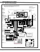
18 Digital Monitoring Products 1k Ω Bell T rouble Bell T rouble Bell B Ð Output Bell B + Output Bell A Ð Output Bell A + Output - Bell Power Ð Input Bell Power + Input Alarm Input Ground Auxiliary Power 10 11 9 7 8 6 5 4 2 3 1 Power Supply Trouble Contacts N/C AUXILIARY POWER SUPPLY 8 7 6 5 4 3 2 1 S S S S S S S 26mA at 12 VDC 85mA at 12865 VDC DMP Model DMP Model 865 S S S S S S 12 or 24 VDC 5 Amp Maximum Notification Circuit Module Notification Circuit Modu
RJ31X Telco Jack MAIN BACKUP 1 2 3 4 5 6 1 2 3 4 Telephone Connections J11 Use EOL Termination Assembly P/N 21024-0003 (590 W 1/2 W Resistor). S Panel Auxiliary Power - Terminal 7 Panel Common - Terminal 10 Supervisory Zone Input - Terminal 13 Note 1 Note 1 Note 1: Use EOL Termination Assembly P/N 21024-0001 (2.2k W 1/2 W Resistor). 10 S 13 S S = Supervised Circuit 19 Digital Monitoring Products WIRING DIAGRAMS 7 23.
24.1 Troubleshooting This section of the Installation Guide provides troubleshooting information for use when installing or servicing an XR6/ XR10 system. Problem Possible Cause Solution J16 reset jumper is installed. Remove the J16 reset jumper. Open or short on the green data wire to the keypad. Check for broken or shorted wires between the keypad and panel. Bad keypad or zone expander. Replace with a new or repaired keypad or zone expander. Keypad display is not functional.