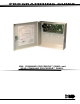
PROGRAMMING GUIDE XR6 COMMAND PROCESSOR™ PANEL and XR10 COMMAND PROCESSOR™ PANEL
MODEL XR6/XR10 COMMAND PROCESSOR PROGRAMMING GUIDE FCC NOTICE This equipment generates and uses radio frequency energy and, if not installed and used properly in strict accordance with the manufacturer's instructions, may cause interference with radio and television reception.
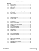
Section TABLE OF CONTENTS Page Introduction 1.1 Before You Begin ............................................................. 1.2 Getting Started .............................................................. 1.3 Programming Menu .......................................................... 1.4 Programmer Lockout Codes ............................................... 1.5 Reset Timeout ................................................................ 1.6 Special Keys ..........................................
Section TABLE OF CONTENTS Page System Reports 5.1 SYSTEM REPORTS ............................................................. 9 5.2 OPENING/CLOSING REPORTS .............................................. 9 5.3 ABORT REPORT ............................................................... 9 5.4 ZONE RESTORAL REPORTS ................................................. 9 5.5 BYPASS REPORTS ............................................................. 9 5.6 CODE CHANGE REPORTS ...................................
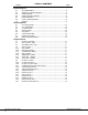
Section TABLE OF CONTENTS Page Zone Information 8.1 ZONE INFORMATION ........................................................ 13 8.2 ZONE NUMBER ............................................................... 13 8.3 ZONE NAME ................................................................... 13 8.4 ZONE TYPE .................................................................... 13 8.5 AREA NAME ................................................................... 13 8.6 ARM AREAS ...........................
This page left intentionally blank.
1 - INTRODUCTION 1.1 Before You Begin About this Guide This guide provides programming information for the DMP XR6/XR10 Command Processor Panel. After this Introduction, the remaining sections describe the functions of each programming menu item along with their available options. Before starting to program, we recommend you read through the contents of this guide. The information contained here allows you to quickly learn the programming options and operational capabilities of the XR6/XR10 panel.
1 - INTRODUCTION 1.3 Programming Menu To select a section for programming, press any top row Select key when the name of that section is displayed on the keypad. The detailed instructions for each programming step are found in the following sections. There are 9 programming menu items to choose from: Menu Item Initialization Communication Remote Options System Reports System Options Section 2 3 4 5 6 Menu Item Output Options Zone Information Stop Set Lockout Code Section 7 8 9 10 1.
1 - INTRODUCTION Select Keys The top row of keys are called the Select keys. When the Programmer displays an option for you to select, such as YES or NO, you press the Select key under the option you want to enable. The Select keys also allow you to change programming information currently in the panel's memory. As you step through each program option, the keypad displays the current information.
2 - INITIALIZATION 2.1 INITIALIZATION INITIALIZATION This function allows you to set the panel's user codes and Programmer selections back to factory defaults before programming the panel for the first time or a new installation. After you select YES to clear a section of memory, the panel asks if you are sure you want to clear the memory. This is a safeguard against accidently erasing the programming. No memory is cleared from the programming until you answer yes to the SURE? YES NO prompt.
3 - COMMUNICATION 3.1 COMMUNICATION COMMUNICATION This section allows you to configure the communication settings for the panel. After choosing the Communication type, continue through the remaining options. 3.2 COMM TYPE: NONE COMMUNICATION TYPE Specifies the communication method the panel uses to contact the receiver. Press any Select key to display the following communication options: NONE DD 4-2 CID NONE - For local systems. Selecting this ends Communication programming.
3 - COMMUNICATION 3.11 O/C USER NO YES OPENING/CLOSING AND USER REPORTS Select YES to enable opening/closing, door access, schedule and code changes, bypass, and zone reset reports by user to be sent to this receiver. 3.12 TEST RPT NO YES TEST REPORT Select YES to enable the Recall Test report to be sent to this receiver. Reports are sent according to the programming in section 3.7 Test Frequency. 3.
3 - COMMUNICATION 3.19 BACKUP NO YES BACKUP REPORTING YES enables this receiver to be a backup to the other receiver in the event the other receiver cannot be reached. 3.20 FIRST PHONE NO. FIRST TELEPHONE NUMBER This is the first number the panel dials when sending reports to this receiver. A phone number can consist of 15 characters in length. You can program a 3-second pause in the dialing sequence by entering the letter P. You can program a dial tone detect by entering the letter D.
4 - REMOTE OPTIONS 4.1 4.2 REMOTE OPTIONS REMOTE OPTIONS This section allows you to enter the information needed for Remote Command/ Remote Programming operation. REMOTE KEY Enter a code of up to 8 digits for use in verifying the authority of an alarm or service receiver to perform a remote command/programming session. The receiver must give the correct key to the panel before allowing access. All panels are shipped from the factory with the Remote Key blank.
5 - SYSTEM REPORTS 5.1 SYSTEM REPORTS 5.2 OPN/CLOS NO YES OPENING/CLOSING REPORTS YES allows the panel to send opening/closing reports by user to the receiver. 5.3 ABORT ABORT REPORT YES allows the panel to send an alarm abort report to the receiver any time an alarm report has also been sent and the Bell Cutoff time has not expired. See Bell Cutoff section 7.2. The area must be disarmed and no alarmed zones can still be armed.
6 - SYSTEM OPTIONS 6.1 6.2 SYSTEM OPTIONS This section allows you to select system-wide functions of the XR6/XR10 system. SYSTEM OPTIONS ALL/PRM NO YES ALL/PERIMETER YES configures the panel as a Perimeter (Area 1) and Interior (Area 2) system. NO configures the panel for Home/Sleep/Away operation. In addition to the Perimeter (Area 1) and Interior (Area 2) a third area, Bedrooms (Area 3) is created. Zones must be assigned to Bedrooms for the area to be active. 6.3 CLS CODE NO YES 6.
7 - OUTPUT OPTIONS 7.1 OUTPUT OPTIONS OUTPUT OPTIONS This function allows you to program the panel's Bell Output functions and certain Output options. Switched Ground (open collector) outputs are available from the XR6/XR10 when using a 4-wire output harness (Model 300 Harness). Refer to the XR6/XR10/XR20/XR40 Installation Guide (LT-0229) for complete information. A description of each output option follows: 7.2 BELL CUTOFF: 15 BELL CUTOFF TIME Enter the maximum time the Bell Output remains on.
7 - OUTPUT OPTIONS 7.5 OUTPUT ACTION . . . OUTPUT ACTION This option allows you to define the operation of the panel's four annunciator outputs. 7.5A CO OUTS: - - - - CUTOFF OUTPUTS Any or all of the available outputs can be programmed here to turn off after the time specified in OUTPUT CUTOFF TIME. See section 7.5B. To disable this option, press any Select key to clear the display of output numbers and then press COMMAND. 7.
8 - ZONE INFORMATION 8.1 ZONE INFORMATION ZONE INFORMATION This allows you to define the operation of each protection zone used in the system. A description of each programming option follows. 8.2 ZONE NO: ZONE NUMBER Enter the number of the zone you intend to program. Press COMMAND to enter a zone name. For instructions on entering alphanumeric characters, see section 1.7. 8.3 NAME: * UNUSED * – ZONE NAME Press the Select key and enter up to 10 characters for the zone name.
8 - ZONE INFORMATION 8.6 ARM AREAS This option specifies the areas to be armed by the Arming Type Zone. When disarmed, all areas in the system are disarmed. ARM AREAS: PERIM ALL HOME SLEEP AWAY PERIMETER/ALL - Specify whether the arming zone arms just the Perimeter (PERIM) or the Perimeter and Interior areas (ALL) for All/Perimeter systems. HOME/SLEEP/AWAY - Specify whether the arming zone arms the Perimeter (HOME), the Perimeter and Interior (SLEEP), or all three areas (AWAY).
8 - ZONE INFORMATION 8.9A MSG: TROUBLE A T L - MESSAGE TO TRANSMIT You can send two report types to the receiver: Alarm and Trouble. These are represented by the characters A and T. Press any top row Select key to display the zone's report options. ALARM - Selecting A, allows an alarm report to be sent to the receiver and the bell output to activate according to zone type. See section 7.4 Bell Action. The zone name appears in the panel's alarmed zones status lists.
8 - ZONE INFORMATION 8.11 ENTRY DELAY: 1 ENTRY DELAY Select the entry delay timer for this zone. Entry delay timers 1 and 2 are programmed in section 6.4 Entry Delay 1. 8.12 CRS ZONE NO YES CROSS ZONE Select YES to enable cross zoning for this zone. Cross zoning requires this zone to trip twice, or this zone and another cross zoned zone to trip, within a programmed time before an alarm report is sent to the receiver.
9 - STOP 9.1 STOP STOP At the STOP prompt, pressing any Select key allows you to exit the Programmer. When selected, the panel performs an internal reset and exits the programmer. The Stop function causes the following to occur: • The system is DISARMED • The panel's Status List is CLEARED During the Stop function, all keypad displays are momentarily blank for two seconds. Once the programming function is terminated, the keypads return to the Status List display. 10 - SET LOCKOUT CODE 10.
11 - APPENDIX 11.1 Status List The Status List is the current status of the system or records of recent system events that are displayed on the alphanumeric keypads. For example, in Home/Away systems, you might see the display SYSTEM READY. This would be the current status of the system. If an event were to occur on the system, such as an AC failure, the keypad would also display the AC POWER -TRBL message.
11 - APPENDIX 11.4 Zone Type Specifications This section describes applications for the default zone types in Zone Information programming. Output Action Message Output Action Message Output Action Message Output Action Swinger Bypass Entry Delay Cross Zone Priority ZONE INFORMATION Message The XR6/XR10 panel contains 11 default zone types for use in configuring the system. These zone types provide the most commonly selected functions for their applications.
11 - APPENDIX 11.5 Zone Type Descriptions NT (Night Zone) - Controlled instant zone used for perimeter doors and windows and interior devices such as PIRs and Glassbreak detectors. DY (Day zone) - Used for emergency doors or fire doors to sound the keypad buzzer and display the zone name when the zone is faulted. Day zones also will send alarm reports to the receiver during the system's armed periods. EX (Exit zone) - Initiates the entry delay timer when its assigned area is fully armed.
11 - APPENDIX 11.7 Default panel programming This program sheets shows the XR6/XR10 panel's default program settings. PROGRAMMING INFORMATION For XR6/XR10 COMMAND PROCESSORTM Panels Name Account Number Address COMMUNICATION Communication Type Account Number Transmission Delay DTMF Defer Recall Test Test Frequency: NONE DD 4-2 CID _ _ _ _ _ (1 to 65,535) _ _ (0 to 60 in 10 sec.
11 - APPENDIX 11.8 4-2 Communication Reports The table below contains a complete list of hexadecimal characters sent using the DMP 4-2 communication format.
11 - APPENDIX 11.10 4-2 Examples The following examples are the actual event codes a central station would receive. The full report would also include the account number and checksum. When the central station receives this event code It means 1A A Fire alarm is being reported on zone 10 2B An Ambush alarm is being reported FB A battery trouble is being reported F9 A Trouble is being reported on zone nine 11.
INTRUSION • FIRE • ACCESS • NETWORKS www.dmp.com 2500 North Partnership Boulevard Made in the USA Springfield, Missouri 65803-8877 LT-0230 (8/02) © 2002 Digital Monitoring Products, Inc.