Digital flatbed cutter G3 series (M-1600, M-2500, L-2500, L-3200, XL-1600, XL-3200, 2XL-1600, 2XL-3200, 3XL-1600, 3XL-3200) Operating manual EN
Translation of the original operating instructions Author Technicak Editorial Department, Zünd Systemtechnik AG Composition and publication Zünd Systemtechnik AG Copyright © Zünd Systemtechnik AG Version: 04 Menu version: 1.40 Date: 02-2009 Doc. no.
0 G3 Series Contents 1 1.1 1.2 1.2.1 1.2.2 1.3 1.4 1.5 1.6 1.6.1 1.6.2 1.6.3 1.7 1.8 1.9 1.10 Introduction . . . . . . . . . . . . . . . . . . . . . . . . . . . . . . . . . . . . . . . . . . . . . . . . .1 Foreword . . . . . . . . . . . . . . . . . . . . . . . . . . . . . . . . . . . . . . . . . . . . . . . . . . . 1 Using the documentation . . . . . . . . . . . . . . . . . . . . . . . . . . . . . . . . . . . . . . 2 Structure of the operating manual . . . . . . . . . . . . . . . . . . . . . . . . . . . .
0 G3 Series 2.8.5 2.8.6 2.8.7 2.8.8 Control unit . . . . . . . . . . . . . . . . . . . . . . . . . . . . . . . . . . . . . . . . . . . . . . . . 18 Performance . . . . . . . . . . . . . . . . . . . . . . . . . . . . . . . . . . . . . . . . . . . . . . . 19 Emissions . . . . . . . . . . . . . . . . . . . . . . . . . . . . . . . . . . . . . . . . . . . . . . . . . 20 FCC approval . . . . . . . . . . . . . . . . . . . . . . . . . . . . . . . . . . . . . . . . . . . . . . 20 3 3.1 3.2 3.3 3.4 3.4.1 3.4.2 3.
0 G3 Series 4 4.1 4.2 4.3 4.3.1 4.3.1.1 4.3.1.2 4.3.1.3 4.3.1.4 4.3.1.5 4.3.1.6 4.3.1.7 4.3.2 4.3.3 4.3.4 4.4 4.4.1 4.4.2 4.4.3 4.4.4 4.4.5 4.4.6 4.5 4.5.1 4.5.2 4.5.3 4.5.4 4.6 4.6.1 4.6.2 4.6.3 4.6.3.1 4.6.3.2 4.6.3.3 4.6.4 4.6.5 4.6.6 4.6.6.1 4.6.6.2 4.6.6.3 4.6.7 4.6.7.1 4.6.7.2 4.6.8 4.6.9 4.7 4.7.1 4.7.2 4.7.3 4.7.4 Controls and operation . . . . . . . . . . . . . . . . . . . . . . . . . . . . . . . . . . . . . . . .1 General . . . . . . . . . . . . . . . . . . . . . . . . . . . . . . . . . . . . . .
0 G3 Series 4.8 4.8.1 4.8.2 4.8.3 4.9 4.9.1 4.9.2 4.9.3 4.10 4.10.1 4.10.2 4.10.3 4.10.4 4.11 4.12 4.13 Feeding options* . . . . . . . . . . . . . . . . . . . . . . . . . . . . . . . . . . . . . . . . . . . . 44 Feeding clamps . . . . . . . . . . . . . . . . . . . . . . . . . . . . . . . . . . . . . . . . . . . . . 45 Feed guide rail . . . . . . . . . . . . . . . . . . . . . . . . . . . . . . . . . . . . . . . . . . . . . 46 Feeding options . . . . . . . . . . . . . . . . . . . . . . . . . . . . . . . . .
0 G3 Series 7.7.11 Draining the maintenance unit condensation water . . . . . . . . . . . . . . . . . 24 7.7.12 Automatic circuit breakers . . . . . . . . . . . . . . . . . . . . . . . . . . . . . . . . . . . . 25 7.7.13 Conveyor belt . . . . . . . . . . . . . . . . . . . . . . . . . . . . . . . . . . . . . . . . . . . . . . 27 7.7.13.1Removing the conveyor belt . . . . . . . . . . . . . . . . . . . . . . . . . . . . . . . . . . . 27 7.7.13.2Remove the covers . . . . . . . . . . . . . . . . . . . . . . . .
0 G3 Series 0-6 000017,02,12-2008, jmu
1 G3 Series Introduction Foreword 1 Introduction Zünd Systemtechnik AG Altstätten, Switzerland 1.1 Foreword Dear customer, By purchasing our product you are participating in the worldwide success of Zünd cutter systems.
1 Introduction G3 Series Using the documentation 1.2 Using the documentation The instruction handbook supplied is intended to help you to: – Operate the machine safely – Perform routine machine maintenance – Use the machine optimally in all permitted areas To do this, you need to be able to find what you want within the documentation.
1 G3 Series Introduction Using the documentation 1.2.2 Symbols Illustration Close, fix, tighten, in Open, release, loosen, out Higher Lower Text structuring Task: Steps to perform Result: Outcome of the tasks performed. Prerequisites for performing a task List of tools Optional accessories There are a number of optional accessories available for the machine. Any description relating to an optional accessory is identified in the operating manual by the * symbol.
1 Introduction Points to note when reading this operating manual 1.3 G3 Series Points to note when reading this operating manual Text references Chapter headings are numbered consecutively, with the first figure corresponding to the chapter number. Where reference is made to sections outside the current chapter, note the first figure and turn to the corresponding chapter, which contains the cited section.
1 G3 Series Introduction Current status of documentation 1.
1 Introduction G3 Series Standardisation, tests, marking Machinery Directive 2006/42/EC and/or without CE marking. As a result, the declaration of conformity must be issued again by the purchaser. 1.6.3 UL testing Zünd G3 cutters have been UL tested and comply with the ISO 60950 standard. The certification can be accessed under UL number E176661.
1 G3 Series Introduction Legal notice 1.7 Legal notice The information contained in this publication is intended for information purposes only and is subject to change without notice at any time. This does not constitute an obligation on the part of Zünd Systemtechnik AG. No part of this document may be copied, distributed, used or disclosed to third parties without express permission. Offenders will be liable for damages. 1.
1 Introduction Publishing details G3 Series 1-8 000009,04,02-2009, jmu
2 G3 Series Product description General 2 2.1 Product description General This chapter contains information on the following: – Representational conventions in the operating manual – Possible uses of the machine – Structure of the main components – Important technical data – General technical description of the device Directional information Directions such as "right, left" or "forwards, backwards" are specified according to the operator's view of the machine during operation. Fig.
2 Product description G3 Series Product identification 2.2 Product identification 2.2.1 Rating plate Important ! The rating plate is used to uniquely identify your machine. Fig.
2 G3 Series Product description Intended use 2.2.2 UL marking Fig. 2-3 UL marking 2.3 1 UL marking (Canada, USA) 3 Max.
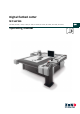
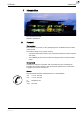
2 Product description G3 Series Cutter - overview 2.4 Cutter - overview Fig.
2 G3 Series Product description Modules, tools 2.5 Modules, tools 2.5.1 General Modules The use of modules and tool inserts means that Zünd cutters can be highly specialised on the one hand, whilst still being able to be easily converted for processing other materials on the other hand. As standard three modules can be fastened onto the module carriage. Instructions on the operation of your module can be found in the chapter "Modules"/"Tool inserts".
2 Product description G3 Series Modules, tools 2.5.2.1 Tools for the UM POT: Pneumatic oscillating tool for thick or tough materials such as foam, filling materials, thick leather, upholstery fabrics etc. EOT: Electrical oscillating tool for cutting soft to average toughness materials.
2 G3 Series Product description Modules, tools 2.5.3 RM-A Router module for the use of 1000 W Zünd motor spindles. Motor spindle with 1000 W for the processing of the most wide-ranging materials. 2.5.4 PUM Punching and stamping module for the processing of leather materials.
2 Product description G3 Series Material handling, options 2.6 Material handling, options 2.6.1 Laser pointer settings The laser pointer is used as an aid for the precise definition of the reference point 2.6.2 ICC camera The ICC camera is used as an aid for importing the registration marks. The processing of the data is dependent on the communication software. 2.6.3 Cutter with static work surface The feeding and removal of the processing material takes place on the work surface of the cutter.
2 G3 Series Product description Material handling, options 2.6.4 Cutter with conveyor Conveyor systems are used for pulling the materials to be worked with. The conveyor belt is used as a cutting base and conveyor belt at the same time. During the processing, the material to be processed is fixed in place using a vacuum. After cutting, the bar moves backwards. The conveyor clamping elements fix the conveyor belt and the feeding clamps are pressed onto the material to be pushed forward.
2 Product description G3 Series Technical description 2.7 Technical description 2.7.1 Complete machine The G3 cutter is a variable processing system for flexible and rigid materials with various tool systems. Extension options are available to provide improved handling and for the adjustment of the system to special requirements or for processing specific materials. 2.7.2 Schedule of work sequences Starting point: CAD/CAM data Communication software (e.g.
2 G3 Series Product description Technical description 2.7.3 Complete machine Table/vacuum plate The work surface is designed as a perforated sheet. Vacuum zones are arranged under this perforated sheet which are connected to a high-performance vacuum generator via a distributor. The vacuum is used for holding down and tightening the material to be processed. The cutter control permits sequential activation/deactivation of the individual vacuum zones and therefore reduces energy consumption.
2 Product description G3 Series Technical description 2.7.4 Movement system The G3 series has four electronically driven axes.
2 G3 Series Product description Technical description 2.7.5 Processing materials The multitude of materials which can be processed with the different module and tool systems means that there is no single way to achieve the target.
2 Product description G3 Series Technical information 2.8 Technical information 2.8.1 Dimensions and weights 2.8.1.1 Basic device Fig.
2 G3 Series Product description Technical information Type Static material clearance width 1 (D) [mm] Material clearance width with CV (D) [mm] M-1600 1610 1330 M-2500 1610 1330 L-2500 2080 1800 L-3200 2080 1800 XL-1600 2550 2270 XL-3200 2550 2270 2XL-1600 3020 2740 2XL-3200 3020 2740 3XL-1600 3490 3210 Material clearance thickness 2 [mm] 61/31 3XL-3200 3490 3210 The work surface and material clearance width are dependent on the tool and the module 1 2 Two versions are av
2 Product description G3 Series Technical information 2.8.1.2 Cutter extension Important ! Cutter extensions do not increase the work surface of the cutter. They serve as a transport belt extension for the feeding and removal of material 2445 CE3200 3145 3XL-3200 CE2500 3XL-1600 1545 2XL-3200 CE1600 2XL-1600 1195 XL-3200 CE1250 XL-1600 L-3200 745 L-2500 CE0800 Type M-2500 Cutter extension T1 [mm] M-1600 Fig.
2 G3 Series Product description Technical information 2.8.2 Electrical connection, power consumption Electrical connection 400 V, 50/60 Hz Value Units Voltage 3-phase, 400 V L1, L2, L3, N, PE Mains frequency Power consumption - 3 phases(without vacuum generator) Current consumption, 3 phases(without vacuum generator) 50/60 Hz 3.6 KW max. 12 A 16 A Mains fuse, min.
2 Product description G3 Series Technical information Conveyor feeding clamps Value Units Setting - pressure regulator maintenance unit (P3) 0.6 MPa Control of vacuum zones, supply of various modules, tools Value Units Operating pressure 0.6 - 0.8 MPa Min. air flow 20 l/min Setting - pressure regulator maintenance unit 0.6 MPa (P2) Additional specifications and requirements can be found in the chapters "Modules, tools, options, material handling" 2.8.
2 G3 Series Product description Technical information 2.8.6 Performance Precision Value Units Resolution of measuring system 0.005 mm Positioning accuracy at a constant temperature ± 0.1 mm Repeat accuracy ± 0.03 mm Evenness of the table ± 0.2 mm Cutting performance Value Speed in the vector direction Units 1 - 1414 mm/s 1 Max acceleration in the vector direction 9.1 m/s2 Max.
2 Product description G3 Series Technical information 2.8.7 Emissions Noise Continuous sound pressure level of the cutter < 75 dB (A) Depending on the tool system and materials to be processed: – if the limit value of 85 dB (A) is exceeded, – noise protection measures may be necessary Important ! Protective measures against noise and emissions (dust, solvents, material residues etc.) for each tool system are specified in chapter 3.
3 G3 Series Safety General 3 3.1 Safety General Your safety – as the operator, service engineer or otherwise – is the primary concern. Certain situations, problems or faults that may occur on the equipment could put your safety at risk if you are not aware of the steps you should take to avoid the resulting dangers.
3 Safety G3 Series Proper use 3.2 Proper use The proper use of the machine is essential for its safe operation. The equipment supplied: • Is listed and labelled • Determines the possible uses of the machine The machine is intended for use as an output device for CAD/CAM data for the labelling and processing of materials arranged on the table.
3 G3 Series Safety Hazard warnings, important instructions 3.4 Hazard warnings, important instructions 3.4.1 Explanation of the hazard warning Both in the operating manual and on the device itself, dangers, important instructions and user tips are designated by special symbols and signal words as follows.
3 Safety Hazard warnings, important instructions 3.4.2 G3 Series Structure of the hazard warnings Example: Warning ! Risk of poisoning from the emission of toxic dust Processing certain materials can lead to the creation of toxic dust with significant risk to health.
3 G3 Series Safety Areas of responsibility 3.5 Areas of responsibility The manufacturer • Is responsible for the safe condition of the machine on delivery, including instruction handbook and accessories, according to the sales documentation.
3 Safety G3 Series Rules and safety at work 3.7 3.8 Rules and safety at work • The operation of the machine is always subject to local regulations regarding safety at work and accident prevention. • Before the machine is put into operation: Always check the safety equipment and protective covers.
3 G3 Series Safety Danger areas 3.9 Danger areas 3.9.1 General danger area Fig.
3 Safety G3 Series Danger areas 3.9.2 Danger area on the module carriage Attention ! Risk of injury on the module carriage The danger area on the module carriage is not secured using safety devices. • Do not reach into the danger area during the manual initialisation • Secure the danger area on the module carriage using the slot protective plates Fig.
3 G3 Series Safety Danger areas 3.9.3 Danger area during the installation Attention ! Risk of injury during the manual initialisation of the tool. The safety devices are not active during the manual initialisation • Do not reach into the danger area during the manual initialisation • Use the automatic initialisation function for the initialisation Fig. 3-3 Danger area during the installation 1 Danger area 3 Example: Module 2 2 Tool (e.g.
3 Safety G3 Series Working and traffic area 3.10 Working and traffic area Warning ! There is a danger of injury to others through inappropriate behaviour or carelessness. Please advise others to maintain an appropriate safety distance from the designated work and traffic zone. Fig.
3 G3 Series Safety Safety signs 3.11 Safety signs 3.11.1 Responsibility of the operator Warning ! Risk of injury due to a lack of safety signs Risks and sources of danger cannot be localised due to the lack of safety signs. • Replace missing or illegible safety signs as per Fig. 3-1 The operator is responsible for replacing missing/illegible safety signs on the machine. The appropriate safety signs can be requested from your service partner. 3.11.2 Position of the safety signs Fig.
3 Safety G3 Series Safety signs Warning ! Safety risks due to missing or illegible safety signs. Check all safety signs on a regular basis for legibility and completeness. Replace missing or illegible safety signs promptly with new original signs.
3 G3 Series Safety Safety signs Warning signs – are triangular and yellow-coloured – Are intended to draw attention to objects and circumstances which represent a potential danger to life and limb.
3 Safety G3 Series Safety and monitoring devices 3.12 Safety and monitoring devices Fig.
3 G3 Series Safety Safety and monitoring devices 3.12.1 Protective system Attention ! If there is a collision, the bar may cause serious injuries. The high level of kinetic energy of the drive results in a braking distance which cannot be ignored. Light barriers and safety cut-offs are no guarantee against injuries. The protective system is made up of protective trip switches and light barriers on the ends of the bar.
3 Safety G3 Series Safety and monitoring devices 3.12.3 Emergency stop switch – Emergency stop switches are part of a protective circuit – They allow the machine to be turned off quickly in hazardous situations Two emergency stop switches can optionally be fitted on the edges of the machine. The mains power supply to the whole machine is switched off as soon as the emergency stop switch is pressed. The operating unit remains switched on.
3 G3 Series Safety Personal protective equipment, clothing 3.13 Personal protective equipment, clothing The safety equipment required for operating the machine is dependent on the following factors: – The module and tool system – The material to be processed When operating the machine or carrying out maintenance or servicing work, wear close-fitting clothing and the appropriate personal protective equipment. Warning ! Risk of injury from being caught or trapped in moving machine parts.
3 Safety G3 Series Mechanical hazards 3.14 Mechanical hazards 3.14.
3 G3 Series Safety Risk of burns 3.14.3 Cuts and stab wounds Knives, routers and punching inserts have very sharp edges which are sometimes hidden by moving equipment (slipper spring). Possible consequences: • Cuts and stab wounds to the hands and arms Precautions during the knife change, initialisation and the operation in the ONLINE operating status of the machine: 3.
3 Safety G3 Series Electrical hazard 3.16 Electrical hazard Warning ! Risk of death or injury from electric shock. The machine is operated with a mains voltage of 380 V, system frequency of 50/60 Hz. Safety instructions • Only trained service personnel are authorised to open switch boxes and electronics units. • Ensure that mains cables are protected against mechanical loading and are laid so that they are free from strain. • Replace damaged cables immediately.
3 G3 Series Safety Risks arising from the emission of toxic dust 3.17 Risks arising from the emission of toxic dust Warning ! Risk of poisoning from the emission of toxic dust Processing the most wide-ranging materials can lead to the creation of toxic dust with significant risk to health. • Obtain information about the toxicity of the material to be processed from the manufacturer. • Use a suitable extraction unit or take other appropriate action accordingly.
3 Safety G3 Series Environmental hazard 3.19 Environmental hazard Warning ! Processing residues, operating fluids etc. can cause damage and pollute the environment if they enter the soil, watercourses or the sewage system. Explanation of the hazard label Hazard label for substances that are harmful to the environment Safety regulations and protective measures • Dispose of waste materials in accordance with current national environmental protection regulations.
3 G3 Series Safety Handling and storage of chemicals 3.20 Handling and storage of chemicals Warning ! Cleaning agents, operating fluids etc., can cause skin irritation and can therefore be hazardous to health if handled carelessly. Always wear personal protective equipment when working with chemicals.
3 Safety G3 Series Risk of fire and explosion 3.21 Risk of fire and explosion Warning ! There is a risk of fire when routing and cutting inflammable materials Terminate the routing/cutting and leave the tool to cool in the case of • Formation of smoke • Discolourations on the router/knife which point to increased heat development Warning ! Risk of dust explosions Flying sparks or electrostatic charges result in the risk that there will be dust explosions during the extraction of different materials.
3 G3 Series Safety Danger caused by laser beam (laser pointer) In the event of a fire: • Switch off the machine (emergency stop switch) • Assess the situation: If the situation is dangerous, leave the area immediately and call the fire brigade. Only try to extinguish the fire if your personal safety is not at risk. • Remove a suitable fire extinguisher (A, B, C) from its bracket and prepare it for use. • Locate the source of the fire.
3 Safety Safety precautions for service personnel 3.24 G3 Series Safety precautions for service personnel The reliability, readiness and service life of the machine greatly depend on you carrying out your work in a conscientious manner. Important ! Specialist knowledge and expertise are required to service and maintain the machine. The manufacturer provides this knowledge through training courses which are specially tailored for service personnel.
4 G3 Series Controls and operation General 4 4.1 Controls and operation General This chapter familiarises you with the controls, guides you through the operational procedures and describes the following operating steps: 4.
4 Controls and operation G3 Series Controls 4.3 Controls 4.3.1 Control panel Fig.
4 G3 Series Controls and operation Controls 4.3.1.1 Operating unit Fig.
4 Controls and operation G3 Series Controls 4.3.1.2 Navigation keys Fig.
4 G3 Series Controls and operation Controls 4.3.1.3 Numerical keys Fig.
4 Controls and operation G3 Series Controls 4.3.1.4 Function keys Fig. 4-5 Function keys Important functions are distributed to the function keys and therefore can be selected directly. It is possible to programme the respective function of the function keys.
4 G3 Series Controls and operation Controls 4.3.1.5 Travel keys Fig. 4-6 Travel keys, shift key 1 Move module forwards 4 Move module to the right 2 Move module to the left 5 SHIFT key 3 Move module backwards These keys are used to move the module unit in the operating statuses STOPPED and OFFLINE. If work is being carried out in the ONLINE operating status and a travel key is pressed then the operating status changes to OFFLINE.
4 Controls and operation G3 Series Controls 4.3.1.6 Soft keys Fig. 4-7 Soft keys These keys change their function depending on the situation. The currently valid function is shown in the display.
4 G3 Series Controls and operation Controls 4.3.1.
4 Controls and operation G3 Series Controls 4.3.2 Emergency stop switch Attention ! Risk of damage to the machine. Only use the emergency stop switches to switch off the machine in an emergency not for standard shutdown. • Emergency stop switches are part of a protective circuit • They allow the machine to be switched off quickly in a dangerous situation Fig. 4-8 Emergency stop switch The machine is fitted with four emergency stop switches as standard.
4 G3 Series Controls and operation Controls Important ! An emergency stop switch that has been pressed remains locked in the off position. To unlock an activated emergency stop switch after regaining operational safety, turn the switch anti-clockwise. Procedure ⇨ When a hazard or a possibly hazardous situation occurs, press an emergency stop switch without delay ✓ All machine movements are stopped.
4 Controls and operation G3 Series Controls 4.3.3 Maintenance unit The maintenance unit adjusts the air pressure to the switching of the vacuum elements/various modules and options. Fig.
4 G3 Series Controls and operation Controls 4.3.4 Interfaces The machine has interfaces for data exchange. These are attached to the electronics unit. Fig.
4 Controls and operation G3 Series Menu navigation 4.4 Menu navigation 4.4.1 Menus and functions Navigation The cutter has a large number of functions. The current menu number and the current menu are displayed in the header. Fig. 4-11 Current menu number, menu Graphic layout Symbol Description Menu Blocked menu (user level) Value/entry/command Display of a value Navigation in the menu ⇨ Use the navigation keys to scroll through the menu and use select a submenu/a function (e.g. Tools).
4 G3 Series Controls and operation Menu navigation Value/entry ⇨ If a flashing cursor appears on the display below a number, then a number input is required ⇨ Enter the required value using the numerical keys ⇨ Check the value and confirm using OK or cancel the entry using ESC Select ⇨ Use the navigation keys to select an entry from the list ⇨ Confirm using OK or cancel using ESC Default settings (factory setting) Default settings are available for many functions/values.
4 Controls and operation G3 Series Menu navigation 4.4.2 Help Help texts are available for important menu entries. In order to display a help text, mark the required menu and press the key. 4.4.3 Info Menu Within the menu the Info Menu can be activated with the key. Use the keys to switch between tabs. Use the down within the tab. keys to scroll up/ Tabs 4.4.
4 G3 Series Controls and operation Menu navigation 4.4.5 User level Access to menus and functions is blocked according to the user level. The user levels have a hierarchical structure. This means that the next highest user also has the access rights to the menu functions that the subordinate user has.
4 Controls and operation G3 Series Menu navigation 4.4.6 Function keys The cutter has function keys (F1 - F8) which can be allocated menu functions. These keys can be selected via the menu or directly.
4 G3 Series Controls and operation Functions 4.5 Functions 4.5.1 Set language It is possible to select the display language of the cutter. ⇨ Select the Language 6-1 function from the menu ⇨ Select the required language from the list and confirm 4.5.2 Set display Setting the contrast Key Description Shift + Increase contrast Shift + Reduce contrast Switch lighting on/off ⇨ Shift + 4.5.3 4.5.
4 Controls and operation G3 Series Operation 4.6 Operation 4.6.1 Daily checks prior to start-up Attention ! There is a risk of injury if the machine is defective. Faults on the machine may be the cause of malfunctions and accidents - never start up a defective machine. • Report all defects and faults to your supervisor and arrange for them to be rectified immediately by qualified personnel.
4 G3 Series Controls and operation Operation 4.6.2 Start-up Switching on the machine Fig. 4-12 Switching on the machine ⇨ Switch the main switch to position ON (1) ✓ The cutter switches on.
4 Controls and operation G3 Series Operation Initialising the machine Attention ! Risk of injury due to automatic starting of the machine Following initialisation, the operating status OFFLINE is active. The cutter can receive commands from the operation software which activate the operating status ONLINE. • Only switch on the operation software following the initialisation of the machine. ⇨ Press the function key .
4 G3 Series Controls and operation Operation 4.6.3 Operating status The cutter can be switched into three operating statuses depending on the purpose: – OFFLINE – ONLINE – STOPPED A combination of keys can optionally be used to switch from any operating status to either of the other two operating statuses. The current operating status is displayed in the header of the main menu and with the LED of the ONLINE key. The following graphic illustrates how the desired operating status is activated.
4 Controls and operation G3 Series Operation 4.6.3.1 OFFLINE Attention ! Risk of injury due to automatic starting of the machine In the OFFLINE operating status, the cutter receives commands from the operating software. These commands can be used to switch to the operating status ONLINE. • Activate the operating status STOPPED during breaks. • Always carry out set-up work in the operating status STOPPED. A red flashing LED on the ONLINE key indicates that the operating status OFFLINE is active.
4 G3 Series Controls and operation Operation 4.6.3.2 STOPPED Important ! The operating status STOPPED protects the operator from the machine being set into motion using remote controls. A red illuminated LED on the ONLINE key indicates that the operating status STOPPED is active. In this operating status, commands (e.g. HPGL) are received but they are not processed. Even commands from the operating software (e.g. to change to the ONLINE operating mode) are ignored.
4 Controls and operation G3 Series Operation 4.6.3.3 ONLINE A green illuminated LED on the ONLINE key indicates that the operating status ONLINE is active. Commands are received and processed in this operating status. ⇨ must be pressed in order to activate the operating status ONLINE. The displays shows the following message: ⇨ Use to switch from the operating status ONLINE to the operating status STOPPED or use to change to the operating status OFFLINE.
4 G3 Series Controls and operation Operation 4.6.4 Moving the bar/module manually Fig. 4-14 Moving the bar/module The module carriage can be moved using the travel keys in the operating status OFFLINE. The assignment of keys corresponds to the direction of travel. Pressing the SHIFT key at the same time will make the module carriage move faster. Pressing travel keys in the X and Y direction at the same time will make the module carriage move diagonally.
4 Controls and operation G3 Series Operation 4.6.5 Tool handling Modules are independently recognised by the cutter control unit. Tools, on the other hand, do not have automatic recognition and must be manually allocated to a module. Tool-specific parameters (initialisation, moving speeds, acceleration) are saved to the corresponding tool and can be called up again at any time. Fig.
4 G3 Series Controls and operation Operation Marking the tools (e.g.) Fig. 4-16 Marking the tool (e.g.) ⇨ Label all tools of the same type with a consecutive number. Appropriate adhesive labels are supplied with the equipment.
4 Controls and operation G3 Series Operation ⇨ All tool types that can be used in the current module are displayed in the popup menu Tool type. Select the tool from this list and confirm using OK ⇨ Enter the appropriate number of the tool in the popup menu Tool number and confirm using OK Select tool ⇨ Inserting the module ⇨ Inserting tool ⇨ Choose Select tool1-1-1-1 in the menu ⇨ Use to change to the Tool menu. All tools already assigned to this module are listed.
4 G3 Series Controls and operation Operation 4.6.6 Modules/tools 4.6.6.1 General Fig. 4-17 Module carriage/module/tool/knife, router etc. 1 Module (e.g.: RM, UM) 2 Tool (e.g.: 1,000 W motor spindle, oscillating tool) 3 Module carriage (e.g.: 3-way) 4 Router, knife etc.
4 Controls and operation G3 Series Operation 4.6.6.2 Inserting/replacing the module Module mount Fig.
4 G3 Series Controls and operation Operation Inserting/replacing the module (e.g. UM) Fig. 4-19 Inserting the module ⇨ Select Change module1-5-1. The module carriage moves to the control panel ⇨ Position the module on the mounting ledge as shown in Fig.
4 Controls and operation G3 Series Operation 4.6.6.3 Tool (e.g. oscillating tool) Ensure, that following preconditions are fulfilled: ❏ The machine is switched off and is in the operating status STOPPED ❏ The module is now mounted and has been located by the control unit Insert and connect the tool Fig.
4 G3 Series Controls and operation Operation 1 Bayonet catch 4 Positioning spindle 2 Module lock 5 Positioning bracket 3 Connector socket ⇨ Move the module to the lower right-hand corner ⇨ Use to switch to the operating status STOPPED ⇨ Insert the selected tool into the module holder. Ensure that the red point on the module is located above the module lock Important ! The tool holder and a holding fixture are each marked with a red dot.
4 Controls and operation G3 Series Operation 4.6.7.1 Connection - electrical tools (EOT, DRT, etc.) Fig.
4 G3 Series Controls and operation Operation 4.6.7.2 Connect pneumatically driven tools Pneumatically driven tools and modules are connected to the interface unit on the module carriage. The pressure is set using a maintenance unit. The air supply is connected to the local installation or supplied via a compressor. The connection data and connection procedure may be found in the operating instructions for the appropriate tool/module.
4 Controls and operation G3 Series Operation 4.6.8 Activating the module It is often useful to activate a module/tool in order to check settings.
4 G3 Series Controls and operation Operation 4.6.9 Tool positions Example: EOT/POT/universal cutting tool Three tool positions are possible following initialisation Fig.
4 Controls and operation G3 Series Material hold-down 4.7 Material hold-down The material is held down via a vacuum. For this purpose, the machine table is divided into 0 - X vacuum zones. The number of zones is dependent on the size of the cutter. The width of the continuously active vacuum zone 0 is 470 m; the width of each additional vacuum zone which can be activated is approx. 80 mm.
4 G3 Series Controls and operation Material hold-down 4.7.1 Preparation Cover the excess vacuum surface in order to achieve optimum material hold-down during the processing procedure. Fig.
4 Controls and operation G3 Series Material hold-down 4.7.2 Defining/checking the vacuum range Fig.
4 G3 Series Controls and operation Material hold-down Check the range ⇨ Use the key to change to the menu Hold down functions3-1 ⇨ Change to the submenu Vacuum range 3-1-1-7 ⇨ Select the function Move to vacuum3-1-1-7-4 ⇨ Choose OK to confirm ✓ The active module moves to the defined vacuum width 4.7.
4 Controls and operation G3 Series Feeding options* 4.8 Feeding options* The Zünd feed system allows the material to be processed to be transported on with a conveyor belt following a completed work process. The conveyor belt is gripped and fed using two clamping elements, while the material to be processed is fixed with feeding clamps/a feed guide rail. The arrangement and activation of the feeding clamps is determined based on the material to be processed.
4 G3 Series Controls and operation Feeding options* 4.8.1 Feeding clamps Fig.
4 Controls and operation G3 Series Feeding options* 4.8.2 Feed guide rail Fig.
4 G3 Series Controls and operation Feeding options* 4.8.3 Feeding options The feed is controlled via the communication software.
4 Controls and operation G3 Series Automatic tool initialisation 4.9 Automatic tool initialisation Important ! Manual initialisation is described in the operating manual of the relevant tool. See chapter "Tools". 4.9.
4 G3 Series Controls and operation Automatic tool initialisation 4.9.2 Setting the height Important ! Ensure that the automatic tool initialisation lies planar on the cutting base (conveyor belt). Adjust the height if necessary. Fig.
4 Controls and operation G3 Series Automatic tool initialisation 4.9.3 Initialisation Example: Module 2; electrically oscillating tool Fig. 4-32 Initialisation ⇨ Use the travel keys to move the module into the centre of the cutter ⇨ Remove the automatic tool initialisation from the holder and position it in the guide on the table.
4 G3 Series Controls and operation Laser pointer, reference point 4.10 Laser pointer, reference point Attention ! Laser class 2. Looking directly into laser beam will damage the eyes. Avoid looking directly into the laser beam. The laser pointer is an optical instrument for visually determining the reference point. It is attached to the module. 4.10.1 Laser pointer settings Fig.
4 Controls and operation G3 Series Laser pointer, reference point 4.10.2 Reference point settings A reference point can be defined on the working area of the cutter. This reference point is the starting point for the processing procedure and corresponds to the zero point of the processing file. Fig.
4 G3 Series Controls and operation Laser pointer, reference point 4.10.3 Choose laser pointer as pointer type Both the current tool and the laser pointer can optionally be defined as the pointer for defining the reference point. ⇨ Select the function Pointer type1-5-2-1-1 ⇨ Select the laser pointer ✓ The laser pointer has been selected and saved as the pointer 4.10.4 Define reference point Example: Active tool = EOT, position: Tool 2-1 Fig.
4 Controls and operation Module carriage slot protective plate 4.11 G3 Series Module carriage slot protective plate Attention ! Risk of being crushed The module carriage area is not monitored by safety devices. • Do not reach into the active area of the cutter during operation • Do not protect occupied slots with slot protective plates On the one hand, the slot protective plate is used as a safety device, and on the other it is used to protect a free module slot from contamination.
4 G3 Series Controls and operation Module and tool holder* 4.12 Module and tool holder* Attention ! Always store any unused tools and modules correctly, in order to avoid any damage to them. Store any unused modules and tools in the module and tool holder. The module and tool holder has space for two tools and two modules. Fig.
4 Controls and operation G3 Series Switch off the machine 4.13 Switch off the machine To switch off the machine, proceed as follows: ⇨ Switch the cutter into the operating status OFFLINE ⇨ Select the function Shut down cutter12 from the menu or press the key combination SHIFT + . ⇨ Use Yes to confirm ⇨ The start page appears on the display. ⇨ Switch off the machine using the main switch. If necessary, secure the main switch using a lock to protect the machine against incorrect commissioning.
5 G3 Series Description of menu General 5 Description of menu Valid from firmware 1.40 5.1 General The menu description contains all menu entries and commands. However, entries which repeat periodically (module 1 - module 4) are only listed once. Explanations on module/tool-specific menu entries can be found in the operating manual of the respective module/tool insert. Menu entries are displayed/faded out depending on the module/tool combination. 5.
5 Description of menu G3 Series Description of menu 5.
5 G3 Series Description of menu Description of menu 1-1-1 Tool pos. 1 No help text is available for this menu. Fig. 5-2 Tool slot, tool assignment e.g. Module 2, tool 1 1 Module 2 (UM) = tool slot 2 2 Oscillating tool = tool 1 = Tool pos. 1 Each module consists of up to four tools (e.g. PUM). The first figure of the menu entry shows the tool slot of the module, the second figure shows the tool position. The menu entries of the tools 11 - 14; 21 - 24; 31 - 34; (41 - 44)* are identical.
5 Description of menu G3 Series Description of menu 1-1-1-1 Select tool No help text is available for this parameter. Assign the tool that is used in the module. For the attachment/selection of a new tool see chapter "Controls and operation", "Tool handling" 1-1-1-2 Initialisation No help text is available for this menu. Setting of the tool working height. Further tool-specific information relating to the initialisation can be found in the operating manual of the respective tool type.
5 G3 Series Description of menu Description of menu Fig. 5-3 Init height ⇨ Select function ⇨ Use the travel keys to move to the suction height and confirm the dialogue using OK 1807 1-1-1-3 Tool setup No help text is available for this menu. Tool-specific settings. These settings are saved for the assigned tool. 3059 1-1-1-3-1 Setup No help text is available for this menu. Tool-specific settings 2139 1-1-1-3-1-1 Tool connector Determining No Connection plug 1the connection for a tool.
5 Description of menu G3 Series Description of menu 1-1-1-3-1-6 Continuous Path No help text is available for this parameter. On Off Continuous path switched on The speed is the same in all directions. The speed can be calculated using the setting value from Down X&Y 1-1-1-3-2-2. Continuous path switched off The speed is calculated from the set axis speed in X and Y direction. 3296 1-1-1-3-1-7 Start with man. Init No help text is available for this parameter.
5 G3 Series Description of menu Description of menu 1-1-1-3-2-4 Lower Z No help text is available for this parameter. Speed when lowering the tool 1115 1-1-1-3-3 Acceleration settings Setting of the tool acceleration. Setting of the tool acceleration.
5 Description of menu G3 Series Description of menu 2888 1-1-1-3-4-7-2 X&Y pressure No help text is available for this parameter. Setting of the pressure in the X and Y direction. Setting range: 2 - 20 kg 2295 1-1-1-3-4-7-3 X pressure Separate setting of the pressure in the direction of the X axis Setting of the pressure for the X axis Setting range: 2 - 20 kg 2296 1-1-1-3-4-7-4 Y pressure Separate setting of the pressure in the direction of the Y axis.
5 G3 Series Description of menu Description of menu Lift-up angle for the automatic raising of the tool in a corner. If a direction change of more than the set value is detected during the cutting process, the tool is raised automatically, turned into the new cutting direction and lowered again. If a direction change of more than the set value is detected during processing, the tool remains in position, is raised, turns into the new processing direction, is lowered again and accelerates. Fig.
5 Description of menu G3 Series Description of menu Delay time for tools which carry out an action after the lowering. E.g. passepartout tool. 1862 1-1-1-3-6-4 After down delay No help text is available for this parameter. Delay before lifting the tool 1863 1-1-1-3-6-5 After up delay No help text is available for this parameter. Delay after lifting the tool 1864 1-1-1-3-6-6 Before up action delay No help text is available for this parameter.
5 G3 Series Description of menu Description of menu Example: 1 Start of cut (penetration point) Cutting diagram with all correction values set to 0 2 End of cut Cutting diagram once the alignment process has been successfully completed Preparation ⇨ Place paper on the cutting support ⇨ Switch vacuum on 5-11 000015,031,02-2009, jmu
5 Description of menu G3 Series Description of menu Correct Y When the axes are aligned, the cuts are moved towards the coordinate system axes until each of the parallel cuts lie on the same axis.
5 G3 Series Description of menu Description of menu Correct X When a centre alignment is carried out, the cuts are moved towards the coordinate system centre until the cut and the coordinate system are congruent.
5 Description of menu G3 Series Description of menu Not active 2662 1-1-2 Tool pos. 2 No help text is available for this menu. Fig. 5-7 Tool slot, tool assignment e.g. Module 2, tool 1 1 Module 2 (UM) = tool slot 2 2 Oscillating tool = tool 1 = Tool pos. 1 Each module consists of up to four tools (e.g. PUM). The first figure of the menu entry shows the tool slot of the module, the second figure shows the tool position.
5 G3 Series Description of menu Description of menu Each module consists of up to four tools (e.g. PUM). The first figure of the menu entry shows the tool slot of the module, the second figure shows the tool position. The menu entries of the tools 11 - 14; 21 - 24; 31 - 34; (41 - 44)* are identical. The allocations and settings of the tools are carried out in the following submenus. 1-2 Module 2 No help text is available for this menu. Menu with settings for module 2. Fig.
5 Description of menu G3 Series Description of menu Each module consists of up to four tools (e.g. PUM). The first figure of the menu entry shows the tool slot of the module, the second figure shows the tool position. The menu entries of the tools 11 - 14; 21 - 24; 31 - 34; (41 - 44)* are identical. The allocations and settings of the tools are carried out in the following submenus. 1-2-2 Tool pos 2 No help text is available for this menu.
5 G3 Series Description of menu Description of menu Fig. 5-12 Tool slot, tool assignment e.g. Module 2, tool 1 1 Module 2 (UM) = tool slot 2 2 Oscillating tool = tool 1 = Tool pos. 1 Each module consists of up to four tools (e.g. PUM). The first figure of the menu entry shows the tool slot of the module, the second figure shows the tool position. The menu entries of the tools 11 - 14; 21 - 24; 31 - 34; (41 - 44)* are identical.
5 Description of menu G3 Series Description of menu Fig. 5-13 Module 1 - 3 1659 1-4-1 Tool pos. 1 No help text is available for this menu. Fig. 5-14 Tool slot, tool assignment e.g. Module 2, tool 1 1 Module 2 (UM) = tool slot 2 2 Oscillating tool = tool 1 = Tool pos. 1 Each module consists of up to four tools (e.g. PUM). The first figure of the menu entry shows the tool slot of the module, the second figure shows the tool position.
5 G3 Series Description of menu Description of menu 1-4-3 Tool pos. 3 No help text is available for this menu. See tool pos 1 1-5 Module carriage No help text is available for this menu. Settings on the module carriage. • Change module • ICC Camera • Laser pointer settings 3040 1-5-1 Change module This function must be called up if a module needs to be installed, dismantled or changed on the module carriage. Procedure for changing the module.
5 Description of menu G3 Series Description of menu No help text is available for this menu. Link to the active tool.
5 G3 Series Description of menu Description of menu 1-6 Table No help text is available for this menu. General table settings 2498 1-6-1 Park options No help text is available for this menu. The parking function is linked to the HP-GL command "PK" in the ONLINE operating status. If this command is triggered, the module carriage moves to the park position. The keys on the operating unit (other than keys 1 - 3) are blocked.
5 Description of menu G3 Series Description of menu 1-6-1-4 X park pos Position after the cutter starts and stand-by position. Definition of the X coordinates of the park position 2500 1-6-1-5 Y park pos Position after the cutter starts and stand-by position. Definition of the Y coordinates of the park position 2470 1-6-2 Light barrier options No help text is available for this menu.
5 G3 Series Description of menu Description of menu Procedure ⇨ Hold a piece of paper between the light barriers that are to be tested ⇨ The display must go from Free to Interrupted If the light barrier is not working then contact your customer service centre. 3188 1-6-2-5-1 Front light barrier No help text is available for this parameter. Error Interrupted Free Testing the front light barrier.
5 Description of menu G3 Series Description of menu • Normal: The material is fed in from the back and removed from the front. • Bidirect 1: The material is fed and removed on the same side. • Bidirect 2: The material is fed and removed on the same side. This process is carried out alternately once at the front and once at the back. 2803 1-7-1-8 Feed comp. Value to compensate for slippage during the page feed. Value for the compensation of the material-dependent track during a feed cycle in mm.
5 G3 Series Description of menu Description of menu 2861 1-7-9 Unwind options No help text is available for this menu. Set universal unwinding unit 3338 1-7-9-1 Unwind options No help text is available for this parameter.
5 Description of menu G3 Series Description of menu 2558 1-7-11-2 Release mode Loosen the feeding clamp with or without shaking. Countermovement Normal Switching countermovement on/off 2559 1-7-11-3 Countermovement No help text is available for this parameter. During the feed, the bar moves the set path backwards in order to ensure that the feeding clamps can be raised. 2594 1-7-11-6 Lower feeding clamps Automatic initialisation with AKI Feeding clamps are lowered to fix the material.
5 G3 Series Description of menu Description of menu 1-7-19 Fusion Feeder No help text is available for this menu. Description to follow 3336 1-7-19-1 Fusion Feeder No help text is available for this parameter. On Off Description to follow 3327 1-7-19-2 Board feeder on Automatic initialisation with AKI Description to follow 3328 1-7-19-2 Board feeder off Automatic initialisation with AKI Description to follow 2953 1-8 Hold down functions No help text is available for this menu.
5 Description of menu G3 Series Description of menu Fig. 5-16 Define vacuum range ⇨ position the active tool above the left edge of the material to be processed ⇨ Choose OK to confirm ✓ The vacuum range has been defined. 1-8-3-3 Active zones Automatic Move to the initialisation end of the with active AKI vacuum zone. The active tool moves to the end of the active vacuum range or to the last active vacuum zone. 2925 1-8-3-5 Active zones No help text is available for this parameter.
5 G3 Series Description of menu Description of menu Fig. 5-17 Vacuum zones (e.g. L-2500) Status display of how many vacuum zones are currently active. 2551 1-8-4 Switch valve options No help text is available for this menu. Settings for controlling the switch valve 2552 1-8-4-1 Switch valve options No help text is available for this parameter. On Off Activating/deactivating switch valve 1-8-4-4 Pulse length Duration of the blowing.
5 Description of menu G3 Series Description of menu 2 Job setup Main menu for the job settings. Settings relating to the current job 1610 2-1 Reference point settings No help text is available for this menu. Two reference points (start points) can be defined on the work surface. The reference point automatically determined by the machine during start-up is deactivated following the activation of a reference point.
5 G3 Series Description of menu Description of menu Menu item has no content. 2-4-1-3 Define rotation centre Determine Move into the therotation rotationcentre centreand of the press job.OK in order to define it. Menu item has no content. 1617 2-4-1-4 Angle No help text is available for this parameter. Menu item has no content. 1615 2-4-1-5 Centre X rotation No help text is available for this parameter. Menu item has no content.
5 Description of menu G3 Series Description of menu The window range is determined by entering two reference points on the working surface.
5 G3 Series Description of menu Description of menu Router is switched off. must be pressed to switch the router on 2635 3-2-1-4 Switch off router Automatic initialisation with AKI Router is switched on. must be pressed to switch the router off 3044 3-2-1-6 EasyDrive on Automatic initialisation with AKI Router converter EasyDrive is switched off.
5 Description of menu G3 Series Description of menu Fig. 5-19 Squares (approx. 10 x 10 mm) distributed over the entire work surface 2269 3-3-3 Circle test cut Automatic Test running... initialisation with AKI For testing modules. Fig. 5-20 Circles (diameter approx. 10 mm) distributed over the entire work surface 2274 3-3-4 Diagonal test cut Automatic Test running... initialisation with AKI For testing the drive elements (belts, bearings, motors) of the X and Y axis.
5 G3 Series Description of menu Description of menu Fig. 5-21 Diagonal over the entire work surface 2275 3-3-5 Random line Automatic Test running... initialisation with AKI Continuous load test Random lines distributed over the entire work surface 2276 3-3-6 Random curve Automatic Test running... initialisation with AKI Continuous load test Random curves distributed over the entire work surface 2277 3-3-7 DIN-Test Automatic Test running... initialisation with AKI Quality test Fig.
5 Description of menu G3 Series Description of menu Fig. 5-23 S test, 140 mm x 240 mm 2805 3-3-9 Move line Automatic Test running... initialisation with AKI as for diagonal test, except with limitation Define line ⇨ Move to starting point, choose OK to confirm ⇨ Move to end point, choose OK to confirm 2270 3-3-11 Module 1 No help text is available for this parameter.
5 G3 Series Description of menu Description of menu On: Module performs test Off: Module does not perform test 2668 3-3-16 Module 6 No help text is available for this parameter. Off On Switch module 6 on/off On: Module performs test Off: Module does not perform test 2669 3-3-17 Module 7 No help text is available for this parameter. Off On Switch module 7 on/off On: Module performs test Off: Module does not perform test 2670 3-3-18 Module 8 No help text is available for this parameter.
5 Description of menu G3 Series Description of menu • AUTO is usually used to automatically determine the optimum white balance. If an optimum result cannot be achieved with AUTO then you can identify the appropriate light source. • Room lighting • Fl. lighting (fluorescent tubes) • Sun 3623 3-5-6 BLC No help text is available for this parameter. On Off The backlight correction (BLC) corrects colour distortions. In the case of reflective materials e.g. the ceiling lighting is reflected.
5 G3 Series Description of menu Description of menu 5 Communication setup Menu for the communication settings such as COM interface, parser etc. Communications settings for parsers, interfaces,... 2279 5-2 Serial interface No help text is available for this menu. Communication settings for the serial interfaces 2280 5-2-1 COM 1 No help text is available for this menu.
5 Description of menu G3 Series Description of menu Communication settings for Ethernet connections 3629 5-3-1 Tool connector No help text is available for this parameter. Entry of the communication port. Default value =50000 3627 5-3-2 IP address No help text is available for this parameter. Display of the IP address 3628 5-3-3 IP template No help text is available for this parameter. Display of the IP template 3661 5-3-4 Unused No help text is available for this parameter.
5 G3 Series Description of menu Description of menu 2618 6-7 Date and time No help text is available for this parameter. Setting the date and the time 2054 6-8 Save panel settings Saves all panel settings such as the function keys, the contrast, the volume etc. Saves all settings for the operating unit. 2056 6-9 Restore panel settings Deletes all saved panel settings and resets them back to a basic value. Resets all settings for the operating unit to a basic value.
5 Description of menu G3 Series Description of menu 8 System info settings No help text is available for this menu. Display of general information about the cutter 2311 8-1 Table type G3_3XL3200 G3_2XL3200 G3_XL3200 G3_L3200 No help text is available for this parameter. G3_3XL1600 G3_2XL1600 G3_XL1600 G3_M2500 G3_L2500 PXN Display of the table type (e.g. L-2500) 2312 8-2 Table number No help text is available for this parameter.
5 G3 Series Description of menu Description of menu Display of the current E-box temperature 2302 8-7 Max E-box temp No help text is available for this parameter. Maximum permitted E-box temperature 3186 8-9 X mot. temp. No help text is available for this parameter. Display of the temperature of the X drive motor 2523 8-10 Actual system outputs No help text is available for this menu.
5 Description of menu Description of menu G3 Series 5-44 000015,031,02-2009, jmu
6 G3 Series Malfunctions Troubleshooting 6 6.1 Malfunctions Troubleshooting Attention ! Risk of injury due to incorrectly remedied faults Ensure that the error on the device is remedied correctly. Contact you Zünd partner. If cutter malfunctions occur and you need the help of our customer service department, make a note of the following details: 6.
6 Malfunctions G3 Series Locate error Error display on the status and error display (example) The error is displayed as a sequence. No redundant figures of the error code will be shown in this display. Example: The error 0x0001D503 is abbreviated to the figures 1D503. If several errors occurred one after the other then these are combined together in a group. The error which occurred first is displayed at the start of the group. All other errors follow in order. Fig.
6 G3 Series Malfunctions Locate error 6.2.2 Error code The error code is made up of a 10-digit, uniquely allocated combination of numbers and letters. The signal word before the error code indicates how serious the error is. Signal Error Information Important information for the operator Caution Notification of possible problems (overheating).
6 Malfunctions G3 Series Error messages 6.3 0x00000603 Error messages Int err.No msg could be sent. Cmd: %0s Index: %1s 7 No help available Contact service 0x00001303 An unknown parameter ID (0x%0s) was requested from the internal database. The parameter is not currently loaded or does not exist. 20 No help available Contact service 0x00004F04 Software exception %1s: %2s 81 No help available Contact service 0x00005403 Unknown command. Cmd ID: %0s.
6 G3 Series Malfunctions Error messages Contact service 0x00007C04 HAL: IO hardware element not loaded. HAL file row number: %0s 127 An IO port wanted to access a processor IO element, but no assignment was available. No IO hardware was assigned to an IO function. Contact service 0x00007D02 HAL: No hardware has been assigned to the virtual object. 129 No help available Contact service 0x00008003 Data initialisation error. 132 Error during the registration of the DB parameters.
6 Malfunctions G3 Series Error messages 0x00009B03 The selected module is not supported. 159 You selected a module that is not supported on this machine. Select an available module and try again. Cause At the moment the selected tool module is still not supported. For example, an attempt was made to change to module 4 even though module 4 is not available on this machine. Solution Select valid module. 0x0000A402 CRC error during transfer.
6 G3 Series Malfunctions Error messages Contact service 0x0000BB04 N status error before loading the Altera. 192 No help available Contact service 0x0000BC04 Altera not ready. 193 No help available Contact service 0x0000BD02 HAL: Err. reading 16 bit value. HAL file row number: %0s 194 An error occurred when reading a16 bit value from the HAL file. The row is discarded. Contact service 0x0000C002 The response to the command was not received in the expected time.
6 Malfunctions G3 Series Error messages Cause It was detected that the head is currently in a hard clipping area. This was probably because a hard clipping window was defined at the point where the head is positioned or because a hard clipping area was activated. Solution The head must be brought out of this area or the hard clipping window must be defined differently. The head can only be moved out of this area manually.
6 G3 Series Malfunctions Error messages Cause Parameters are currently being edited on another operating unit. While this is happening no data can be edited on a second operating unit Solution Wait until the editor is closed on the other operating unit. Attempt another time. 0x0000FB01 This user level requires a password. 260 A password must be entered in order to enter the requested user level. Use the parameter password. The parameter editor is opened directly when you press information.
6 Malfunctions G3 Series Error messages Contact service 0x00011F02 The command may not be carried out in this operating status. Change the operating status in order to carry out the command. 296 Cause The instruction was discarded because it is not permitted in the current instruction mode. Solution Switch the system to the operating status OFFLINE or ONLINE and carry out the instruction again.
6 G3 Series Malfunctions Error messages 0x00012C04 Axis inspection err. Axis %0s Error %1s 310 An error Each Axis: The Error 0x1 0x2 0x4 0x8 zero min max Override corresponding code: halfcurrent occurred current reference byte stands not exceeded during mark error reached forcode the Error an axis inspection stands which formay ofthis thehave axis. axes. an 0=X, The error. 1=Y motor etc.or encoder may be incorrectly connected. Contact service 0x00012F02 HAL: Not possible to configure the IO.
6 Malfunctions G3 Series Error messages Contact service 0x00014501 Operating status in the process of changing. 338 Wait until the status changes. Contact service 0x00014B03 Incorrect sequencer status 344 Incorrect sequencer status for the command %0s. Contact service 0x00014C03 Peripheral could not be entered into the list. 345 Remove a peripheral element that is no longer needed. Contact service 0x00014D02 Peripheral could not be found in the peripheral list.
6 G3 Series Malfunctions Error messages Cause The system status may not be changed because the system is in the operating status STOPPED. It is only possible to leave the operating status STOPPED using operating unit 1. Solution Change operating status via operating unit 1. 0x00015502 Incorrect parameter for the arc command. 354 Check the parameters of the arc command. Cause An attempt was made to draw a circle. The transferred parameters do not correspond with the definition.
6 Malfunctions G3 Series Error messages 0x00015E01 Press the ONLINE key to repeat the output. 363 The last plotter data was reloaded. Pressing the ONLINE key will mean that they are processed again. Cause Message to the user after the replot command. The user will be prompted to press the Online key so that the replot can be carried out. 0x00016002 Curve vector length too short. 365 Curve length smaller than the look ahead length. Contact service 0x00016202 Error when setting a sub-instruction.
6 G3 Series Malfunctions Error messages 0x00017103 Temperature too high in the electronics unit. The system may be damaged. Temperature %0s °C. 382 The temperature in the electronics unit exceeded a critical threshold. Check that the fan is not covered. Check the fan filter and replace it if it is contaminated. Cause The temperature in the BF board exceeded a critical threshold. This may cause damage to the hardware. Solution Switch machine off and leave to cool down.
6 Malfunctions G3 Series Error messages 0x00018003 Distance outside of range. 398 Module change difference is outside of the range. Error index = %0s. Contact service 0x00018202 Initialisation module stopped. 400 Carry out reinitialisation. Cause The initialisation of a module was interrupted. The head modules are set to an uninitialised status and can no longer be moved. Solution The initial status can be reproduced by carrying out a reinitialisation of the head.
6 G3 Series Malfunctions Error messages 0x00018D03 Tool overcurrent. 412 Overcurrent detected on the tool insert. Cause An overcurrent error occurred in the tool. Solution Pull the tool out of the material. 0x00018E03 Excess module temperature. 413 The module insert has got too hot. Cause The module is too hot. Solution Wait until the module has cooled down. 0x00019003 Communication between the panel and MC interrupted. 415 No help available Contact service 0x00019103 Unknown module position.
6 Malfunctions G3 Series Error messages Cause A virtual module is selected. It is not possible to move the axes with this module. The virtual module is selected if a select pen is set on a module which is not available on the active head. Solution Select valid module. 0x00019C03 Terminator characters not permitted. 428 The following characters are not permitted:sign = 17 XONsign = 19 XOFFsign = 27 ESCsign = 64 '@' Contact service 0x00019D02 Unknown machine ID.
6 G3 Series Malfunctions Error messages 439 No help available Contact service 0x0001A803 HAL: Unknown Altera string. HAL file row number: %0s 440 No help available Contact service 0x0001A903 HAL: It is not possible to configure a stop trigger at this Altera input. HAL file row number: %0s 441 No help available Contact service 0x0001AA03 HAL: Bit does not exist. HAL file row number: %0s 442 No help available Contact service 0x0001AB03 HAL: Insufficient bits available for the assigned function.
6 Malfunctions G3 Series Error messages Cause An attempt was made to use a router converter on two different tools at the same time. 0x0001B303 Timeout when starting the router. 451 No help available Cause The router could not reach its speed after being switched on. 0x0001B403 Router overloaded. Could not keep up the specified speed. 452 No help available Cause The router has deviated too much from the target speed and has therefore been stopped.
6 G3 Series Malfunctions Error messages 0x0001BD03 Hardware not available. 461 It has been determined that an attempt was made to access unavailable hardware. Contact service 0x0001BE03 Error in the user data command. Cmd:%1s Tsk:%2s 462 Check the content and the size of the user data. Contact service 0x0001BF02 AKI not available. 463 Install and configure automatic initialisation tool. Cause AKI not available Solution Connect AKI and activate.
6 Malfunctions G3 Series Error messages 0x0001C704 Parameter transfer complete. Restart the cutter in order to use the new parameters. No help available 0x0001C803 AKI in the park station. 473 Remove automatic initialisation tool from the park station. Cause The AKI must not be in the park station during use. An attempt was made to carry out tool initialisation even though the AKI is still in the park station. Solution Position AKI on the table 0x0001C903 AKI not in the park station.
6 G3 Series Malfunctions Error messages Cause The power unit is too hot, the cutter must be switched off and the problem in the power unit must be remedied. Solution It may be the case that the ventilation in the power unit is not correct. Check for dirt and clean if necessary. 0x0001D303 Unauth. mod. change This can lead to hazardous situations. Always use "Start module change" to assemble or dismantle modules.
6 Malfunctions G3 Series Error messages 0x0001DE03 The Z link synchronisation has not come about. 502 No help available Contact service 0x0001DF04 The sequencer task has not started. The Altera is therefore not ready. 503 No help available Contact service 0x0001E002 Unstable controller parameters.
6 G3 Series Malfunctions Error messages Cause An excessive temperature was measured on the X motor. Solution 0x0001EE03 • Wait until the temperature has cooled down. • Check the sensor. Excess temperature X axis motor. 518 No help available Cause X motor displays an excess temperature. Solution Wait until the temperature reduces. 0x0001EF03 No sealing air available. 519 No help available Cause Sealing air is not (no longer) available. Solution Check sealing air.
6 Malfunctions G3 Series Error messages Contact service 0x0001F703 The speed requirement could not be reached. 527 No help available Cause The speed requirement of the router was not reached. 0x0001F803 Altera ZERO pointer. 528 No help available Contact service 0x0001FA03 Error when writing data via Z link. Index: %0s 530 No help available Contact service 0x0001FB03 Error when reading data via Z link. Index: %0s 531 No help available Contact service 0x0001FC01 OptionBoard (Str1A) not available.
6 G3 Series Malfunctions Error messages 0x00020503 PWM control over-modulated. The parameters must be adjusted. 545 No help available Contact service 0x00020603 Aux drive %0s not ready. 546 No help available Contact service 0x00020704 Comm to Y board interrupted. 547 No help available Contact service 0x00020803 Overload detected on OptionBoard. String no. = %0s. Driver no. = %1s. 548 String 1 2 3 4 5 6 -> String no.: 3 1B 2 A Contact service 0x00020903 Incompl HP-GL comm Data may have been lost.
6 Malfunctions G3 Series Error messages 0x00021A03 New mod. board FW does not match installed mod. type. installed: %2s 567 No help available Contact service 0x00021B03 Trans Altera file not recognised. 568 No help available Contact service 0x00021C03 No data for update. 569 No help available Contact service 0x00021E01 OptionBoard (Str1A) not available. Take-up/unwind units therefore deactivated. 571 No help available Contact service 0x00022401 Error during camera communication.
6 G3 Series Malfunctions Error messages 0x00022F02 Please insert the PUM into another slot. 596 The PUM is not supported on the first slot. 0x00023003 The received front end command does not correspond to the syntax: Error after command: %2s 597 No help available 0x00023203 This front end command is not permitted in this status: %2s 599 No help available 0x00023301 OptionBoard (Str1A) not available. The external feed stop has therefore been deactivated.
6 Malfunctions Error messages G3 Series 6-30 000012,03,02-2009, jmu
7 G3 Series Cleaning and maintenance General 7 7.1 Cleaning and maintenance General – This chapter describes (in tabular form) all the maintenance jobs which are required for the machine. – The maintenance list only affects the basic unit. Maintenance activities for modules, tool inserts and options can be found in the respective operating manual. – Maintenance jobs that operators can carry out themselves are specially indicated and are described in more detail in this chapter.
7 Cleaning and maintenance G3 Series Safe maintenance of the machine 7.2 Safe maintenance of the machine General safety instructions • Servicing and repair work must be carried out by trained specialist personnel. • For periodic checks/inspections you must comply with the mandatory intervals or the intervals specified in the instruction manual. Equipment appropriate to the task must be available in order to carry out maintenance tasks.
7 G3 Series Cleaning and maintenance Operating resources 7.3 Operating resources 7.3.1 Handling operating materials Following the instructions for handling operating materials carefully will increase the reliability and service life of the machine. Follow the regulations for handling chemicals, particularly cleaning fluid and lubricants. Environmental protection • Always take care to protect the environment • Observe the disposal regulations applicable in your country.
7 Cleaning and maintenance G3 Series Operating resources 7.3.2 Cleaning fluids Attention ! The use of incorrect cleaning fluids not approved by Zünd will damage the machine. Only use cleaning fluids recommended by Zünd Systemtechnik. Do not use abrasive cleaning fluids. Caustic substances and scouring agents can damage surfaces of the cutter (e.g. operating unit). 7.3.
7 G3 Series Cleaning and maintenance Steps for maintenance 7.4 Steps for maintenance Different types of symbols (circle, box, star – solid; circle, box, star – outline) divide the service and maintenance tasks into two groups. Meaning of symbols: Outline symbols: {, • , This service and maintenance work is carried out by authorised service personnel of Zünd Systemtechnik.
7 Cleaning and maintenance G3 Series Steps for maintenance Work to be carried out By personnel By authorised maintenance personnel z One-off activity { One-off activity Repetitive interval Repetitive interval If necessary If necessary Chapter Special intervals Annually (2000 h) Monthly Weekly Daily Maintenance/inspection during operating hours General Visually check the machine for damage Free the machine of dust and processing residue Check electrical equipment (options) t
7 G3 Series Cleaning and maintenance Steps for maintenance Work to be carried out By personnel By authorised maintenance personnel z One-off activity { One-off activity Repetitive interval Repetitive interval If necessary If necessary Chapter Special intervals Annually (2000 h) Monthly Weekly Daily Maintenance/inspection during operating hours Check alignment of toothed/steel belt and readjust if necessary Check tension of toothed/steel belt and readjust if necessary Check the belt te
7 Cleaning and maintenance G3 Series Lubrication diagram 7.5 Lubrication diagram Lubricate all lubricating points indicated in the lubrication diagram in accordance with the specified maintenance intervals. The machine is lubricated using Klüberoil 4UH1®. Fig. 7-1 Lubricating points 7.
7 G3 Series Cleaning and maintenance Accessories case Contents Accessories Amount Activity Allen screwdriver 4 x 170 mm Qty. 1 Assemble/disassemble modules Vacuum element spacers Qty. 6 Service/Installation Adhesive tape; width 19 mm Qty. 1 Service/Installation Teflon grease 20 ml Service Soldering fluid brush Qty. 1 Service Qty. 1 Change conveyor belt Qty. 1 Change conveyor belt Qty.
7 Cleaning and maintenance G3 Series Maintenance jobs 7.7 Maintenance jobs 7.7.1 Service flaps and covers Fig.
7 G3 Series Cleaning and maintenance Maintenance jobs 7.7.2 Maintenance position Warning ! Danger of injury The cutter may be put into operation by third parties. • Always place the cutter in the maintenance position before carrying out maintenance work! Unless expressly required otherwise, move the machine to the maintenance position before starting maintenance work. Fig. 7-3 Secure the machine 7.7.3 – Switch off the machine using the main switch.
7 Cleaning and maintenance G3 Series Maintenance jobs 7.7.4 Clean the machine Zünd cutters are production machines that are subject to enormous amounts of stress on a daily basis. Keeping the machine clean will help to keep operation as free from interruption as possible. Important ! Do not use compressed air to clean the machine. Loose cuttings and other dirt will end up in the bearings and drive belts and damage them.
7 G3 Series Cleaning and maintenance Maintenance jobs 7.7.5 Clean X axis guide rails Tools and materials # Lubricant for guide rails, bearings # Clean, lint-free rags # 4 mm Allen key Ensure, that following precondition is fulfilled: ❏ The machine is in the maintenance position. Remove the covers Fig.
7 Cleaning and maintenance Maintenance jobs G3 Series Cleaning the guide rails Fig.
7 G3 Series Cleaning and maintenance Maintenance jobs 7.7.6 Oil X axis guide bearings Tools and materials # Lubricant for guide rails, bearings # Greasing set for X axis guide rails, bearings # 4 mm Allen key # Clean, lint-free rags Ensure, that following precondition is fulfilled: ❏ The machine is in the maintenance position. Remove the covers Fig.
7 Cleaning and maintenance Maintenance jobs G3 Series Guide bearings Fig. 7-7 Guide bearings The bar is mounted with 2 guide bearings on a guide rail on each side. Oil these bearings at intervals according to the maintenance schedule.
7 G3 Series Cleaning and maintenance Maintenance jobs Lubricating the lubrication points Fig.
7 Cleaning and maintenance Maintenance jobs G3 Series ⇨ Screw the lubrication connection of the lubrication set onto the guide rails behind the bar (A, B) ⇨ Press the syringe until the feed line is ventilated ⇨ Position the guide bearings above the lubrication connection (C) ⇨ Use the syringe to insert approx.
7 G3 Series Cleaning and maintenance Maintenance jobs 7.7.7 Cleaning/oiling Y axis guide rails Tools and materials # Lubricant for guide rails, bearings # 4 mm Allen key # Clean, lint-free rags Ensure, that following preconditions are fulfilled: ❏ The machine is in the maintenance position. ❏ All modules have been dismantled from the module carriage. Remove the covers Fig.
7 Cleaning and maintenance Maintenance jobs G3 Series Cleaning the guide rails Fig.
7 G3 Series Cleaning and maintenance Maintenance jobs 7.7.8 Lubricating the Y axis bearing Tools and materials # Lubricant for guideways # 4 mm Allen key # Clean, lint-free rags # Cardboard base or drip tray Ensure, that following preconditions are fulfilled: ❏ The machine is in the maintenance position. ❏ All modules have been dismantled from the module carriage. Lubricate bearing Fig.
7 Cleaning and maintenance Maintenance jobs 7.7.9 G3 Series Clean the chipping protection brush Ensure, that following precondition is fulfilled: ❏ The machine is in the maintenance position. Cleaning the brush Fig.
7 G3 Series Cleaning and maintenance Maintenance jobs 7.7.10 Cleaning the feeding clamps/feed guide rail Tools and materials # Lint-free cloth # Spirit Ensure, that following precondition is fulfilled: ❏ The machine is in the maintenance position. Procedure Fig.
7 Cleaning and maintenance Maintenance jobs 7.7.11 G3 Series Draining the maintenance unit condensation water Tools and materials # Container Ensure, that following precondition is fulfilled: ❏ The machine is switched off. Procedure Fig. 7-14 Drain condensation water Disposal ! The condensation liquid from the water separator is contaminated with oil. Therefore the liquid must be disposed of correctly according to the specific national regulations.
7 G3 Series Cleaning and maintenance Maintenance jobs 7.7.12 Automatic circuit breakers Attention ! Danger of injury by electric shock Hazardous voltage in the power unit • Do not remove the power box cover under any circumstances. • Contact your service partner if you have any problems with the energy supply. Attention ! Danger of machine damage If an automatic circuit breaker has been triggered then there is an electrical defect in a consumer.
7 Cleaning and maintenance G3 Series Maintenance jobs Automatic circuit breakers Fig.
7 G3 Series Cleaning and maintenance Maintenance jobs 7.7.13 Conveyor belt Tools and materials # Conveyor belt # Stapler with suitable staples (6 mm) # Applicator gun # 2 component adhesive (cartridge) # Spatula # Masking tape (2 cm wide) # Gaffer tape # Industrial scissors Ensure, that following precondition is fulfilled: ❏ The machine is switched off. 7.7.13.1 Removing the conveyor belt Undoing the tensioning screws Fig.
7 Cleaning and maintenance Maintenance jobs G3 Series Removing the conveyor belt ⇨ Cut the conveyor belt using scissors and remove it ⇨ Dispose of the conveyor belt correctly 7.7.13.2 Remove the covers Fig.
7 G3 Series Cleaning and maintenance Maintenance jobs 7.7.13.3 Fitting a conveyor belt Important ! Conveyor belt installation is dependent on the direction of movement. Pay attention to the marks on the belt and ensure that the belt is fitted correctly. Determining conveyor direction Fig. 7-19 Determining conveyor direction 1 Conveyor belt roll 2 Conveyor direction ⇨ Unroll the conveyor belt as shown in Fig. 7-19. A upper side. The points in the feed direction.
7 Cleaning and maintenance G3 Series Maintenance jobs Feeding through the conveyor belt Fig. 7-20 Feeding through the conveyor belt 1 Conveyor belt 3 Guide rollers 2 Guide rollers, front, rear 4 Guide rollers Important ! Turn on the vacuum when feeding through the conveyor belt to prevent it slipping. ⇨ Feed through the conveyor belt as shown in Fig. 7-20.
7 G3 Series Cleaning and maintenance Maintenance jobs Gluing the conveyor belt Attention ! toxic fumes • Do not breath in glue fumes • Only use glue in well ventilated rooms Attention ! Skin bonding or being irritated by glue • Do not allow glue to come into contact with skin • Do not ingest glue or allow to come into contact with mucous membranes Use chemical-proof protective gloves when gluing the conveyor belt. Fig.
7 Cleaning and maintenance Maintenance jobs G3 Series Fig.
7 G3 Series Cleaning and maintenance Maintenance jobs 1 Assembly base 5 Masking tape, layer 1 2 Adhesive tape 6 Masking tape, layer 2 3 Conveyor belt 7 Applicator gun with 2-component glue 8 Spatula 4 Stapler ⇨ Set up the conveyor belt straight and fix in place with adhesive tape. If necessary, turn on the vacuum to prevent the conveyor belt slipping. Push the assembly base under the fixed conveyor belt. (A) ⇨ Align the other end of the conveyor belt parallel to the fixed edge with a gap of approx.
7 Cleaning and maintenance Maintenance jobs G3 Series Tensioning the conveyor belt Fig.
7 G3 Series Cleaning and maintenance Instructions for disposal 7.8 Instructions for disposal Important ! Contact Zünd customer services or your service partner before you dispose of your cutter. Zünd cutters are modern industrial devices which correspond with the current standards and guidelines on the disposal of old appliances. • Plastic components > 20 grams are labelled and can therefore be disposed of correctly.
7 Cleaning and maintenance Starting up after periods at a standstill G3 Series 7-36 000001,07,12-2008, jmu
8 G3 Series Tools 8 Tools 8-1 000005,03,12-2008, jmu
8 Tools G3 Series 8-2 000005,03,12-2008, jmu
9 G3 Series Modules 9 Modules 9-1 000004,03,12-2008, jmu
9 Modules G3 Series 9-2 000004,03,12-2008, jmu
10 G3 Series Options 10 Options 10-1 000007,03,12-2008, jmu
10 Options G3 Series 10-2 000007,03,12-2008, jmu
11 G3 Series Material handling 11 Material handling 11-1 000006,03,12-2008, jmu
11 Material handling G3 Series 11-2 000006,03,12-2008, jmu
12 G3 Series Additional specifications 12 Additional specifications 12-1 000008,03,12-2008, jmu
12 Additional specifications G3 Series 12-2 000008,03,12-2008, jmu
13 G3 Series Documents 13 Documents 13-1 000029,02,12-2008, jmu
13 Documents G3 Series 13-2 000029,02,12-2008, jmu
14 G3 Series Glossary 14 Glossary User level The menu has a hierarchical division into user levels. Each user level can be activated by entering a password. Operating status ONLINE Jobs are processed in this operating status. Operating status OFFLINE In this operating status, data are received but not processed. In this operating status it is possible to use remote controlled commands to switch to the operating status ONLINE. Operating status STOPPED No data are received in this operating status.
14 Glossary G3 Series Modules Modules serve as the interface between the cutter and the tool. Emergency stop Emergency stop switches are safety elements which cause the immediate switching off of the machine in hazardous situations. Numerical keys Keys for making numerical entries on the operating unit. Parser Program that can break down any input and convert it into a format that can be used for further processing. Popup Window that is released by the menu.