• W A R N I N G • This manual contains information on limitations regarding product use and function and information on the limitations as to liability of the manufacturer. Installation Manual PC5132-433 Version 4.
WARNING Please Read Carefully Note to Installers This warning contains vital information. As the only individual in contact with system users, it is your responsibility to bring each item in this warning to the attention of the users of this system. System Failures This system has been carefully designed to be as effective as possible. There are circumstances, however, involving fire, burglary, or other types of emergencies where it may not provide protection.
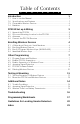
Table of Contents C O N T E N Introduction 1.1 1.2 1.3 1.4 7 11 Test the Reception of Wireless Devices ............................................. 11 Mount the PC5132 and Wireless Devices .......................................... 13 Additional Notes 6.1 6.2 6.3 4 Program Zones and Partitions .............................................................. 7 Enable PC5132 Supervision ................................................................. 7 Enable Supervision of Wireless Zones ........
Thank you for purchasing the PC5132 Wireless Receiver. This product is the result of several years of development and will allow you to connect up to 32 wireless detection devices to the PC580, PC1555, and the Power series control panels. The PC5132 uses 433 MHz.
Introduction S E C T I O N 1 This manual describes how to install, program and maintain the PC5132. Before you install the PC5132 module, you should complete the following steps in your system installation: 1. Plan the installation and wiring of the security system (see your system Installation Manual). 2. Install the control panel, and install and enroll at least one keypad to use for programming. 3. Install and enroll any hardwired zone expander modules (PC5108) you plan to use.
I N T R O D U C T I O N 1.3 Compatible Wireless Devices Please refer to the Instruction sheets of the following devices for more information. The PC5132 v4.0 can receive signals • WLS904-433 Motion Detector • WLS906-433 Smoke Detector • WLS925L-433 Transmitter from the following devices: • WLS912-433 Glass Break Detector* • WLS914-433 Pet-Immune PIR* • WLS909-433 Wireless Key *When available 1.
PC5132 Set up & Wiring S E C T I O N 2 This section describes how to set up and wire the PC5132 module. 2.1 Unpack the PC5132 Check that the following parts are in your PC5132 package: • PC5132 PCB • Diversity antennae • PC5132 plastic cabinet • Hardware for mounting the cabinet 2.2 Choose a Mounting Location for the PC5132 NOTE: Mount the PC5132 receiver and wireless devices after you have done placement tests with the wireless devices (see sections 5.1 and 5.2).
Enrolling Wireless Devices S E C T I O N 3 This section describes how to enroll wireless devices (WLS904-433, WLS906433 and WLS925-433), and wireless keys (WLS909-433). For more information on these devices, read the instruction sheet included with each device. 3.1 A Note about Electronic Serial Numbers An electronic serial number (ESN) is printed on the back of each wireless device. ESNs are used to enroll the wireless devices with the PC5132 receiver.
W I R E L E S S D E V I C E S 3.3 Enroll & Program Wireless Keys (WLS909-433) For wireless keys to work on the system, you need to enroll them and then program the function buttons. Wireless keys are not assigned to zones and require no zone programming. You can enroll up to 16 wireless keys on the system. Enroll Wireless keys 1. At a system keypad, enter [✱][8][Installer’s code] to go to the Installer’s Programming section. 2. Enter programming section [804]. 3.
W I R E L E S S D E V I C E S 5. Record your programming choices in the worksheets in the back of the manual. 6. To exit press [#]. 3.4 Identified Wireless Keys Reporting by the system of openings/closings by individual wireless keys and command output [✱][7] activation by wireless key buttons may be supported on certain control panels. To do this, the system will reserve access codes 17 – 32 for wireless keys 01-16 respectively.
Other Programming S E C T I O N 4 4.1 Program Zones and Partitions Now that you have enrolled the wireless devices, you should complete all zone programming on the system. Although the exact programming required varies depending on which control panel the PC5132 is connected to, you should check that the following programming areas are completed correctly for each wireless zone: • Enable zones and/or assign zones to one or more partitions (programming sections [201]-[209]).
O T H E R P R O G R A M M I N G If the PC5132 module does not show on the keypad, one of the following conditions may be present: • the module is not connected properly to the Keybus • there is a problem with the Keybus wiring run • the module does not have enough power • no devices have been enrolled on the PC5132 4.3 Enable Supervision of Wireless Zones NOTE: (for PC5010 v1.
O T H E R P R O G R A M M I N G 4.4 RF Jam Detect Zone For RF jamming detection to work, you must select an unused zone to be used as the RF Jam Detect zone. When the receiver detects an attempt to jam the RF signal, the RF Jam Detect zone will be violated and the system will generate a tamper signal. When the jamming signal is gone, the RF Jam Detect zone closes and the system sends a tamper restore signal. To enable RF jamming detection: 1. Enter [✱][8] [Installer’s Code]. 2.
O T H E R P R O G R A M M I N G 4.6 Deleting Wireless Devices To remove a wireless device from the system, follow the guideline for enrolling a wireless device (see section 3.2). Program the ESN as [000000]. The wireless device for the zone will be removed. NOTE: You may need to remove power from the panel in order to clear troubles caused by deleted zones. Now that you have completed all PC5132 related programming, you can test and mount the receiver and devices.
Testing & Mounting S E C T I O N 5 5.1 Test the Reception of Wireless Devices It is very important to test the proposed placement of each wireless device before it is mounted. Following these steps will test the signal strength between the PC5132 and the wireless devices. You can test all of the devices together (global placement testing) or test each device individually. To test all the devices together, see ‘Testing All Wireless Devices Together’ below.
T E S T I N G & M O U N T I N G WLS909-433: Press any function key at several different locations. Read the test results at the keypad: Result LED Keypad LCD Keypad Buzzer/Bell Good Light 1 On Steady “Good” 1 Beep/Squawk Bad Light 3 On Steady “Bad” 3 Beeps/Squawks Activate the device until you get 3 ‘good’ results in a row. You may mount the WLS devices where results were good. Devices indicating a bad result must be moved to another location.
T E S T I N G & M O U N T I N G 5.2 Mount the PC5132 and Wireless Devices When you have tested reception of the PC5132 with all the wireless devices (see section 5.1) and you have a good mounting location, mount the PC5132: 1. Pull the Keybus wires through the hole at the bottom of the cabinet. 2. Mount the cabinet securely to the wall. Mount the Devices If you have conducted the placement test described in section 5.
Additional Notes S E C T I O N 6 6.1 Trouble Conditions The control panel always watches for possible trouble conditions. If a trouble condition occurs, the keypad “Trouble” light will turn on and the keypad will beep. Press [✱][2] to display the trouble conditions. The following trouble conditions apply to the PC5132 and/or any enrolled devices. General System Tamper - This trouble is generated when the PC5132 plastic cover is removed.
A D D I T I O N A L N O T E S Replacing Batteries in Wireless Devices 1. Remove the cover of the device from its back plate. This creates a tamper condition on the zone. 2. Refer to the battery installation instructions on the installation sheet of each component. Be sure to note the proper orientation of the batteries as you install them. 3. When the fresh batteries are in place, re-attach the cover to the back plate.
Troubleshooting S E C T I O N 7 1. When I enter the 2-digit zone number when adding a wireless device, the keypad gives me a long beep. You cannot enter ESNs unless a PC5132 wireless receiver is connected to the Keybus. See section 2 for instructions on setting up and wiring the PC5132 module. 2. I have entered the ESN for the device but when I violate the device, the zone does not show open on the keypad.
Programming Worksheets S E C T I O N 8 [804] 5132--433 Wireless Expansion Programming • 6-digit entry is required. See Section 3.1 “A note on Electronic Serial Numbers” for details on programming 6-digit serial numbers.
P R O G R A M M I N G W O R K S H E E T Wireless Key Serial Numbers Default = 000000 [41] Key 01 l_____l_____l_____l_____l_____l_____l [42] Key 02 l_____l_____l_____l_____l_____l_____l [43] Key 03 l_____l_____l_____l_____l_____l_____l [44] Key 04 l_____l_____l_____l_____l_____l_____l [45] Key 05 l_____l_____l_____l_____l_____l_____l [46] Key 05 l_____l_____l_____l_____l_____l_____l [47] Key 07 l_____l_____l_____l_____l_____l_____l [48] Key 08 l_____l_____l_____l_____l_____
P R O G R A M M I N G W O R K S H E E T S Partition 1 Wireless Key Options Default = 00 [59] Function Key 1 Function Key 2 l____l____l Function Key 3 l____l____l l____l____l Function Key 4 l____l____l l____l____l Function Key 3 l____l____l l____l____l Function Key 4 l____l____l Partition 2 Wireless Key Options [60] Function Key 1 Function Key 2 Supervision [81] Wireless Supervisory Window l____l____l Default = 96 The window is programmed in 15 minute increments.
P R O G R A M M I N G W O R K S H E E T S [84] Zone Device Supervision Options (17-24) Default = ON Option ON Option OFF l________l Option 1 Zone 17 Supervision enabled Disabled l________l Option 2 Zone 18 Supervision enabled Disabled l________l Option 3 Zone 19 Supervision enabled Disabled l________l Option 4 Zone 20 Supervision enabled Disabled l________l Option 5 Zone 21 Supervision enabled Disabled l________l Option 6 Zone 22 Supervision enabled Disabled l
P R O G R A M M I N G W O R K S H E E T S l________l Option 4 Wireless Key 04 on partition 2 On partition 1 l________l Option 5 Wireless Key 05 on partition 2 On partition 1 l________l Option 6 Wireless Key 06 on partition 2 On partition 1 l________l Option 7 Wireless Key 07 on partition 2 On partition 1 l________l Option 8 Wireless Key 08 on partition 2 On partition 1 [92] Wireless Keys (9-16) Partition Assignments Default = OFF Option ON Option OFF l________l O
Guidelines for Locating Smoke Detectors A PS PE CE TN I DO IN X 9 A Experience has shown that all hostile fires in family living units generate smoke to a greater or lesser extent. Experiments using typical fires in family living units indicate that detectable quantities of smoke precede detectable levels of heat in most cases. In existing homes, NFPA Standard 72 requires that a smoke detector be installed outside each sleeping area and on each additional story of the family unit.
Index I N D E X A G R add device 4 wireless key antenna 3 global placement test 10 removing device 9 module 7 RF jamming 9 5, 11 B batteries replacing 13 buttons programming 5 C I individual placement test 11 interference 3 J jamming signal detection 8, 12 connect Keybus 3 receiver 3 K D location choosing 3 low battery devices 12 default module 9 panel 9 delete device 9 devices 2 adding 4 removing 9 distance from control panel 1 E electronic serial number 4 enroll device 4 PC5132 7 wire
LIMITED WARRANTY Digital Security Controls Ltd. warrants the original purchaser that for a period of twelve months from the date of purchase, the product shall be free of defects in materials and workmanship under normal use. During the warranty period, Digital Security Controls Ltd. shall, at its option, repair or replace any defective product upon return of the product to its factory, at no charge for labour and materials.
N O T E S
N O T E S
FCC COMPLIANCE STATEMENT CAUTION: Changes or modifications not expressly approved by Digital Security Controls Ltd. could void your authority to use this equipment. This equipment generates and uses radio frequency energy and if not installed and used properly, in strict accordance with the manufacturer’s instructions, may cause interference to radio and television reception.
©2000 Digital Security Controls Ltd. Toronto, Canada 1-800-387-3630 • www.dscgrp.