GE Power Controls Ed. 02 We bring good things to life. GE Power Controls in Europe Breakers New Air400Circuit - 4000A GE Power Controls is the European arm of GE Industrial Systems, one of the ten core businesses of the General Electric Company (USA), known internationally for its positive approach to its customers, its people and the world we all live in.
M-PACT
Air circuit breakers 400A-4000A A.4 A.5 A.6 A.8 A.14 A.22 Fixed Circuit Breaker Withdrawable Circuit Breaker Characteristics M-PRO Microprocessor Protection Relays M-PRO Trip Curves M-PACT Accessories Technical overview A Order codes B Wiring diagrams Dimensional drawings C Numerical index X A.
Notes A.
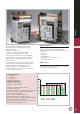
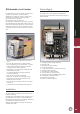
M-PACT Rated from 400 to 4000A the M-PACT circuit breaker has been designed to meet the most stringent demands in fault detection and safe interruption thereof. Available in 2 frame sizes: - frame size 1 ranging from 400 to 2500A - frame size 2 ranging from 800 to 4000A The range has been developed to be aesthetically and technically co-ordinated with other protective devices within the GE Power Controls industrial product ranges.
Technical over view Fixed circuit breaker Power Supply All M-PACT fixed pattern air circuit breakers incorporate a stored energy mechanism. The spring can be charged either manually or electrically via a motor operator that is automatically activated after the closing operation. IP43 front panel and door escutcheon seals are standard features with IP20 protected secondary isolating contacts. For enhanced protection, an optional IP54 door panel is also available.
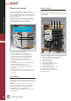
Withdrawable circuit breaker All stated short circuit ratings are certified with incoming supply connection made to either upper or lower terminals. 4 5 M-PACT Pre-mounted into a self-contained ’cassette’, this versatile circuit breaker can be inserted or withdrawn via sliding rails using a racking drive mechanism controlled by a racking handle. It provides three set positions: Disconnected / Test / Connected.
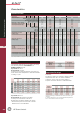
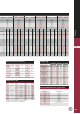
Characteristics Performance Data Technical over view Characteristic Rated current (40°C) A Symbol Units In A Endurance (number of operating cycles) Mechanical (with maintenance) Mechanical (without maintenance) Electrical (at rated current) Rated service voltage (50/60 Hz) Ue V Rated insulation voltage (50/60 Hz) Ui V Rated impulse withstand voltage Uimp V Number of poles Rating of 4th pole ACB type Frame size 400 630 800 1000 20000 10000 5000 690 1000 8000 20000 10000 5000 690 1000 8000 20000 10
1600 1600 2000 2000 2500 2500 3200 3200 4000 4000 20000 10000 5000 690 1000 8000 20000 10000 5000 690 1000 8000 20000 10000 5000 690 1000 8000 20000 10000 5000 690 1000 8000 20000 10000 5000 690 1000 8000 20000 10000 5000 690 1000 8000 S 1 3&4 100% N 1 H 2 S 1 3&4 100% N 1 H 2 S 1 3&4 100% N 1 H 2 S 1 3&4 100% N 1 H 2 S 2 3&4 100% N 2 H 2 S 2 3&4 100% N 2 H 2 50 50 50 50 40 65 65 65 50 40 80 80 80 65 60 50 50 50 50 40 65 65 65 50 40 80 80 80 65 60 50 50 50 50 40 65 65 65
Technical over view M-PRO Microprocessor Protection Relays M-PRO17, M-PRO20, M-PRO30 and M-PRO40 are the dedicated protection and management units for the M-PACT air circuit breakers and have been developed to meet the most stringent demands of modern circuit protection.
Making Current Release (MCR) Instantaneously trips the M-PACT air circuit breaker should an attempt be made to close onto a shortcircuit fault current greater than the detected making capacity of 50kA. This trip becomes inoperative once the circuit breaker has been closed. High Set Instantaneous Short Circuit (HSISC) Provides immediate protection against high value short circuit currents by tripping the circuit breaker. HSISC pickup level is factory set depending on M-PACT air circuit breaker performance.
Technical over view Neutral pole protection M-PRO17: Factory-set to 50% or 100% M-PRO20-40: Customer selectable between ‘OFF’, 50% and 100%. Thermal memory To protect against unacceptable recurring or cyclic overloads the M-PRO will track and memorise the thermal effects of load current while the breaker is on line. Tripping will be initiated when the cumulative thermal effect of cyclic overloading reaches a predetermined level.
M-PRO Microprocessor Protection Relays - Specifications 17 M-PRO 20 30 40 L H L H ● ● ● ● ● ● ● ● ● ● ● ● ● ● ● ● ● ● ● ● • 0.1 times selected long time ● ● ● ● ● • Pick-up, 1.5, 2, 3, 4, 6, 8, 10 and 12 x Ir ● ● ● ● ● ❍ ● ● ● ● Long Time Protection • Pickup adjustable from 0.4 to 1.0x In in steps of 0.1 ● • Pickup adjustable from 0.4 to 1.0x In in steps of 0.
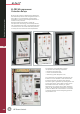
Technical over view M-PRO17 Microprocessor Protection Relay 1 M-PRO20-40 Microprocessor Protection Relays 3 2 3 4 5 1 6 4 2 5 7 6 8 7 8 A MPRO17 shown with UEF 1. Overload rotary setting switch 2. Short circuit and time delay rotary setting switches 3. Earth fault and time delay rotary setting switches 4. Selectable manual reset button 5. Overload and short circuit protection curve symbol 6. Earth fault protection curve symbol 7. Healthy LED 8.
Plug-in Portable Test Unit (PTU) Plug-in Portable Power Box (PPB) M-PACT MPRO17 test box shown above Specially designed for reliable testing of the MCR and HSISC protection systems on each phase, by means of tertiary injection. The test unit is also used to prove both overcurrent and earth fault pick-up levels.Can also be employed to test for tripping in order to verify efficient microprocessor operation. The test unit incorporates a set of rechargeable batteries and includes a charger unit as standard.
Trip Curves Technical over view M-PRO 17 Time to trip in seconds (s) A Current I (x Ir, the sensor rating) A.
Trip Curves M-PRO 17 M-PACT Time to trip in seconds (s) A Current I (x Ir, the sensor rating) A.
Earth Fault Protection Curves M-PRO 17 Waar komt deze tekst? Technical over view LT set at 1 x ACB rating (Ir) Time to trip in seconds (s) A Current I (x Ir, the sensor rating) A.
Earth Fault Protection Curves M-PRO 17 M-PACT Time to trip in seconds (s) A Current I (x Ir, the sensor rating) A.
Trip Curves Technical over view M-PRO 20/30/40 LT set at 1 x ACB rating, In LTD set at 30 s SC set at 6 x Ir SCD = 3 s ST set at 12 x Ir STD set at 1 s Type H: Instantaneous release at 80kA A Time to trip in seconds (s) LT set at 1 x ACB rating, In LTD set at 0.2 s ST set at 1.5 Ir STD set at Inst Type S: Instantaneous release at 50kA LTD has 16 available settings 0.25...35 seconds at 7.2 x Ir Indicated: 0.2 and 30 seconds SC has 8 available settings 1.
Trip Curves M-PRO 20/30/40 M-PACT LT set at 1 x ACB rating (In) LTD set at 35 s SC set at 6 x Ir SCD = 3 s ST set at 12 x Ir STD set at 300 ms Type H: Instantaneous release at 80kA Time to trip in seconds (s) LTD has 16 available settings 0,25...35 seconds at 7.2 x Ir Indicated: 5 and 35 seconds A LT set at 1 x ACB rating, In LTD set at 5 s ST set at 1.5 Ir STD set at 300 ms Type S : Instantaneous release at 50kA SC has 8 available settings 1.
Technical over view Earth Fault Protection Curves M-PRO 30/40 Earth fault pick up If Adjustment = 0.1 to 1.0 x In in 0.01 x In steps Pickup If set at 1 x In Cropping set at 6 Time delay set at 1 s Time to trip in seconds (s) A Earth fault cropping C Trip Time = Time delay x C x If/I Adjustment = 1, 1.5, 2, 2.5, 3, 4, 5 & 6 Note: 1 = OFF Indicated: C = 1.5 and 6 Pickup If set at 0.1 x In Time delay set at 0.1 s Time delay has 11 settings Inst. to 1 s in steps of 0.1 s Indicated: Inst., 0.
Earth Fault Protection Curves M-PRO 30/40 (tolerance bands shown) Earth fault pick up If Adjustment = 0.1 to 1.0 x In in 0.01 x In steps M-PACT Pickup If set at 1 x In Cropping set at 6 Time delay set at 1 s Time to trip in seconds (s) A Earth fault cropping C trip Time = Time delay x C x I f/I Adjustment = 1, 1.5, 2, 2.5, 3, 4, 5 & 6 Note: 1 = OFF Indicated: C = 1.5 and 6 Pickup If set at 0.1 x In Time delay set at 0.1 s Time delay has 11 settings Inst. to 1 s in steps of 0.1 s Indicated: Inst., 0.
Technical over view M-PACT Accessories A A wide range of optional accessories have been developed that are compatible with all M-PACT air circuit breakers, regardless of nominal rating or frame size. Each one incorporates ‘easy-fit’ design features for quick installation, either in the factory or by the user on site. before further closure is attempted, and a cut-off is instigated should a closing signal be maintained.
Auxiliary switches The M-PACT circuit breaker is equipped with 5 NO and 3 NC auxiliary switches as standard. Maximum number of contacts is 8, for alternative configurations please contact for availability. Mechanical operation counter Lock and key types Castell: Type FS1 lock with key type FK4 key, 45° clockwise rotation to trap the key, 7/8"x3/8" square spindle. Ronis: Type 1104B lock with standard key, 1/4" turn rotation to trap the key, compulsory spindle size.
Technical over view Cable/busbar earthing device All ‘M-PACT’ circuit breakers can be fitted with an earthing device. It has a short circuit fault capacity equal to the Icw rating of the breaker. This permits either the feeder cables or the busbar to be safety held at earthed potential and locked during system maintenance operations. Carriage position switch A Cluster contacts These are the main isolating contacts which are fitted to the rear terminals on the moving portion of the withdrawable unit.
Interlocks Mechanical interlocks can be fitted to the following electrical systems and can link 2 and/or 3 circuit breakers. Any nominal rating, frame size, number of poles or type (fixed pattern or withdrawable) can be interlocked. Typical circuit Interlock configuration Possible combinations Type A 1 from 2 way interlock 2 cable configuration Interlocking between 2 circuit breakers. Type B 1 from 3 way interlock 6 cable configuration Interlocking between 3 circuit breakers.
Technical over view Circuit breaker insertion interlock the unit should it be outside its cassette. Installers will also find it particularly valuable for top-tier mounted circuit breakers. Note: Users who already possess a ‘Titan’ handling truck for the original M-PACT circuit breaker can now obtain a conversion kit. By incorporating this optional security interlock device into a system, it prevents the inadvertent insertion of an incorrectly rated withdrawable circuit breaker into a cassette.
Accessories Performance Data Device Auxiliary & carriage switch Motor operator Closing coil Shunt trip Auxiliary power unit 250 220 - 250 110 - 127 220 - 250 110 - 130 220 - 250 110 - 130 380 - 440 220 - 250 110 - 130 95 - 265 125 250 220 - 250 110 - 127 42 - 48 24 - 36 220 - 250 110 - 130 40 - 48 24 - 30 220 - 250 110 - 130 40 - 48 24 - 30 110 - 130 42 - 48 24 - 30 24 - 264 Operating range Power consumption (Watts max.) Rating (Amps resistive) - - 0.85 to 1.1 times rated voltage 350 0.
Specify on the order 1. Device 2. Rating Order codes 3. Number of poles 4. System 5. Frequency 6.Type B B.
B.0 Specify on the order B.2 Air Circuit Breaker - TYPE S - 50kA - Non-auto B.4 Air Circuit Breaker - TYPE S - 50kA - Automatic B.6 Air Circuit Breaker - TYPE N - 65kA - Non-auto B.8 Air Circuit Breaker - TYPE N - 65kA - Automatic B.10 Air Circuit Breaker - TYPE H - 80kA - Non-auto B.12 Air Circuit Breaker - TYPE H - 80kA - Automatic B.14 M-PRO Protection B.15 M-PRO Electrical Accessories B.16 M-PRO Mechanical Accessories B.
Air Circuit Breaker - TYPE S - 50kA - Non-auto Basic circuit breaker manually operated, non automatic, 5 NO and 3 NC auxiliary switches. Withdrawable pattern – basic circuit breaker and cassette with flat copper terminals rear connected. Fixed pattern – basic circuit breaker with rear terminals horizontal.
Front Access Connections Fixed pattern TOP connections BOTTOM connections Frame size Rating (A) Poles Cat. No. Ref. No. Cat. No. Ref. No.
Air Circuit Breaker - TYPE S - 50kA - Automatic Basic circuit breaker manually operated automatic (with protection), 5 NO and 3 NC auxiliary switches. Withdrawable pattern - basic circuit breaker and cassette with flat copper terminals rear connected. Fixed Pattern - basic circuit breaker with rear terminals horizontal.
Front Access Connections Fixed pattern TOP connections BOTTOM connections Frame size Rating (A) Poles Cat. No. Ref. No. Cat. No. Ref. No.
Air Circuit Breaker - TYPE N - 65kA - Non-auto Basic circuit breaker manually operated, non automatic, 5 NO and 3 NC auxiliary switches. Withdrawable pattern – basic circuit breaker and cassette with flat copper terminals rear connected. Fixed pattern – basic circuit breaker with rear terminals horizontal.
Front Access Connections Fixed pattern TOP connections BOTTOM connections Frame size Rating (A) Poles Cat. No. Ref. No. Cat. No. Ref. No.
Air Circuit Breaker - TYPE N - 65kA - Automatic Basic circuit breaker manually operated automatic (with protection), 5 NO and 3 NC auxiliary switches. Withdrawable pattern - basic circuit breaker and cassette with flat copper terminals rear connected. Fixed Pattern - basic circuit breaker with rear terminals horizontal.
Front Access Connections Fixed pattern TOP connections BOTTOM connections Frame size Rating (A) Poles Cat. No. Ref. No. Cat. No. Ref. No.
Air Circuit Breaker - TYPE H - 80kA - Non-auto Basic circuit breaker manually operated, non automatic, 5 NO and 3 NC auxiliary switches. Withdrawable pattern – basic circuit breaker and cassette with flat copper terminals rear connected. Fixed pattern – basic circuit breaker with rear terminals horizontal.
Cassette only Basic cassette with flat copper terminals rear connected. Frame size Rating (A) Poles Cat. No. Ref. No. 2 800 to 3200 2 4000 3 4 3 4 MH32C32 MH42C32 MH32C40 MH42C40 405357 405356 405359 405358 M-PACT Moving Portion only Basic circuit breaker manually operated, non automatic, 5 NO and 3 NC auxiliary switches and cluster contacts.
Air Circuit Breaker - TYPE H - 80kA - Automatic Basic circuit breaker manually operated, automatic (with protection), 5 NO and 3 NC auxiliary switches. Withdrawable pattern - basic circuit breaker and cassette with flat copper terminals rear connected. Fixed Pattern - basic circuit breaker with rear terminals horizontal.
Cassette only Basic cassette with flat copper terminals rear connected. Frame size Rating (A) Poles Cat. No. Ref. No. 2 800 to 3200 2 4000 3 4 3 4 MH32C32 MH42C32 MH32C40 MH42C40 405357 405356 405359 405358 M-PACT Moving Portion only Basic circuit breaker manually operated, non automatic, 5 NO and 3 NC auxiliary switches and cluster contacts.
M-PRO Protection Order codes M-PRO Protection Relay B Type Cat. No. Ref. No.
M-PRO Optional Protection(1) Cat. No. Ref. No.
Mechanical Accessories Type A - 2 way interlock 2 way Interlocking Frame size Type 1 Withdrawable Fixed 2 Withdrawable Fixed Order codes Cable Poles 3 4 3 4 3 4 3 4 Type B - 1 from 3 way interlock Rod Cable Ref. No. Cat. No. Ref. No. Cat. No. Ref. No. Cat. No. Ref. No.
Spare parts Neutral / Earth Leg (4th) Current Transformer with mounting kit Rating (A) Cat. No. Ref. No. 1 2 1 2 1 2 1 2 1 2 1 2 2 2 800 ELCT8001 ELCT8002 ELCT10001 ELCT10002 ELCT12501 ELCT12502 ELCT16001 ELCT16002 ELCT20001 ELCT20002 ELCT25001 ELCT25002 ELCT32002 ELCT40002 405683 405713 405684 405714 405685 405715 405686 405716 405687 405717 405688 405718 405689 405690 1000 1250 1600 2000 2500 3200 4000 M-PACT Frame size Neutral (4th) Rogowski Coil with mounting kit* Frame size Rating (A) Cat.
Spare parts (continued) Cluster Contacts Frame size 1 1 2 2 1 1 2 2 2 2 Rating (A) ACB Type Cat. No. Ref. No. 2 2 2 2 2 2 2 2 2 2 CLCS116 CLC125 CLC232 CLC240 CLCN116 CLC125 CLC232 CLC240 CLC232 CLC240 UNIPLIER 405769 405771 405772 405773 405770 405771 405772 405773 405772 405773 405800 Cat. No. Ref. No.
C.3 Wiring Diagrams C.3 Circuit breakers C.4 M-PRO 17 relay C.5 M-PRO 20/30/40 relay Dimensional drawings Circuit Breaker - Type S - 50kA C.6 Horizontal, Rear Access Connection - Fixed Pattern C.9 Rear Access Connection - Withdrawable Pattern C.13 Front Access Connection - Withdrawable Pattern C.15 Front Access Connection - Fixed Pattern Circuit Breaker - Type N - 65kA C.18 Horizontal, Rear Access Connection - Fixed Pattern C.21 Rear Access Connection - Withdrawable Pattern C.
Wiring Diag rams Notes C C.
Wiring Diagram M-PACT Terminal References B1 to B16 C1 to C16 D1 to D6 D7 to D12 D13 to D18 Automatic disconnect L.T. blocks Automatic disconnect L.T. blocks Carriage switch blocks for disconnected position(1) Carriage switch blocks for test position(1) Carriage switch blocks for connected position(1) (1) Changeover contacts can be reconfigured by user.
Wiring Diag rams Wiring Diagram M-PRO 17 C C.
Wiring Diagram M-PRO 20/30/40 M-PACT Connections for M-PRO 20/30/40 Terminal Terminal C Terminal Location M-PRO 20 M-PRO 30 M-PRO 40 PAMM PAMM PAMM PAMM PAMM PAMM PAMM PAMM PAMM PAMM PAMM PAMM PAMM PAMM PAMM LT ‘B’ block LT ‘B’ block LT ‘B’ block LT ‘B’ block A14 A15 B5 B6 A1 A2 A3 A4 A5 A6 A7 A8 A9 A10 A11 A12 A13 A14 A15 B3 B4 B5 B6 A1 A2 A3 A4 A5 A6 A7 A8 A9 A10 A11 A12 A13 A14 A15 B3 B4 B5 B6 Function OUTPUT 4, normally open volt free contact: Operates when the REF (or SEF) element trips t
Horizontal, Rear Access Connection Type S - 3 pole - Frame size 1, In = 400A to 1600A (max) Minimum space to earth metal and for arc chute removal 182 Min Arc chute removal Insulated metal or insulated sheet (customer supplied) Centre line of operating panel Centre line of operating panel Fascia centre Dimensional Drawings Fixed Pattern Fascia centre 100 to door ACB fascia cut-out dimensions The cut-out dimensions give an approximate nominal clearance of 3mm around ACB fascia.
Horizontal, Rear Access Connection Fixed Pattern Type S - 3 pole - Frame size 1, In = 2000A and 2500A (max) Insulated metal or insulated sheet (customer supplied) Minimum space to earth metal and for arc chute removal 182 Min Arc chute removal Centre line of operating panel M-PACT Fascia centre Centre line of operating panel Fascia centre 100 to door ACB fascia cut-out dimensions The cut-out dimensions give an approximate nominal clearance of 3mm around ACB fascia.
Horizontal, Rear Access Connection Type S - 3 pole - Frame size 2, In = 2000A to 4000A (max) Insulated metal or insulated sheet (customer supplied) Minimum space to earth metal and for arc chute removal 182 Min Arc chute removal Centre line of operating panel Centre line of operating panel Fascia centre Dimensional Drawings Fixed Pattern Fascia centre 100 to door ACB fascia cut-out dimensions The cut-out dimensions give an approximate nominal clearance of 3mm around ACB fascia.
Rear Access Connection Withdrawable Pattern Type S - 3 pole - Frame size 1, In = 400A to 1600A (max) Minimum clearance to cassette side. 382 to door Fascia centre Ventilation Fascia centre 35 Test 50 Disconnected 275 Fully withdrawn Centre line of operating panel Connected 414 M-PACT Centre line of operating panel ACB fascia cut-out dimensions The cut-out dimensions give an approximate nominal clearance of 3mm around ACB fascia.
Rear Access Connection Type S - 3 pole - Frame size 1, In = 2000A & 2500A (max) Minimum clearance to cassette side. 382 to door Fascia centre Ventilation Centre line of operating panel Fascia centre Dimensional Drawings Withdrawable Pattern 35 Test 50 Disconnected 275 Fully withdrawn Centre line of operating panel Connected 414 ACB fascia cut-out dimensions The cut-out dimensions give an approximate nominal clearance of 3mm around ACB fascia.
Rear Access Connection Withdrawable Pattern Type S - 3 pole - Frame size 2, In = 2000A to 3200A (max) Minimum clearance to cassette side. 382 to door Fascia centre Ventilation Fascia centre 35 Test 50 Disconnected 275 Fully withdrawn Centre line of operating panel Connected 414 M-PACT Centre line of operating panel ACB fascia cut-out dimensions The cut-out dimensions give an approximate nominal clearance of 3mm around ACB fascia.
Rear Access Connection Type S - 3 pole - Frame size 2, In = 4000A (max) Must not be removed or fitted horizontally Minimum clearance to cassette side. Fascia centre 382 to door Ventilation Centre line of operating panel Fascia centre Dimensional Drawings Withdrawable Pattern 35 Test 50 Disconnected Centre line of operating panel Connected 414 275 Fully withdrawn ACB fascia cut-out dimensions The cut-out dimensions give an approximate nominal clearance of 3mm around ACB fascia.
Front Access Connection Withdrawable Pattern Type S - 3 pole - Frame size 1, In = 400A to 1600A (max) M-PACT ACB fascia cut-out dimensions The cut-out dimensions give an approximate nominal clearance of 3mm around ACB fascia. These sizes are for guidance and can be scaled if a different aperture is required. Type S - 4 pole - Frame size 1, In = 400A to 1600A (max) C ACB fascia cut-out dimensions The cut-out dimensions give an approximate nominal clearance of 3mm around ACB fascia.
Front Access Connection Dimensional Drawings Withdrawable Pattern Type S - 3 pole - Frame size 1, In = 2000A & 2500A (max) ACB fascia cut-out dimensions The cut-out dimensions give an approximate nominal clearance of 3mm around ACB fascia. These sizes are for guidance and can be scaled if a different aperture is required. Type S - 4 pole - Frame size 1, In = 2000A & 2500A (max) C ACB fascia cut-out dimensions The cut-out dimensions give an approximate nominal clearance of 3mm around ACB fascia.
Front Access Connection Fixed Pattern Type S - 3 pole - Frame size 2, In = 3200A & 4000A (max) Insulated metal or insulated sheet (customer supplied) Minimum space to earth metal and for arc chute removal 182 Min Arc chute removal Minimum clearance to breaker side. Fascia centre M-PACT 100 to door Fascia centre ACB fascia cut-out dimension The cut-out dimensions give an approximate nominal clearance of 3mm around ACB fascia.
Front Access Connection Type S - 3 pole - Frame size 1, In = 400A to 2500A (max) Minimum clearance to cassette side. 382 to door Fascia centre Dimensional Drawings Withdrawable Pattern Connected 414 50 Disconnected 35 Test Fascia centre ACB fascia cut-out dimensions The cut-out dimensions give an approximate nominal clearance of 3mm around ACB fascia. These sizes are for guidance and can be scaled if a different aperture is required.
Front Access Connection Withdrawable Pattern Type S - 3 pole - Frame size 2, In = 3200A & 4000A (max) Minimum clearance to cassette side. M-PACT Fascia centre 382 to door Connected 414 50 Disconnected 35 Test Fascia centre ACB fascia cut-out dimension The cut-out dimensions give an approximate nominal clearance of 3mm around ACB fascia. These sizes are for guidance and can be scaled if a different aperture is required.
Horizontal, Rear Access Connection Type N - 3 pole - Frame size 1, In = 400A to 1600A (max) Minimum space to earth metal and for arc chute removal 182 Min Arc chute removal Insulated metal or insulated sheet (customer supplied) Centre line of operating panel Centre line of operating panel Fascia centre Dimensional Drawings Fixed Pattern Fascia centre 100 to door ACB fascia cut-out dimensions The cut-out dimensions give an approximate nominal clearance of 3mm around ACB fascia.
Horizontal, Rear Access Connection Fixed Pattern Type N - 3 pole - Frame size 1, In = 2000A and 2500A (max) Minimum space to earth metal and for arc chute removal 182 Min Arc chute removal Insulated metal or insulated sheet (customer supplied) Centre line of operating panel M-PACT Fascia centre Centre line of operating panel Fascia centre 100 to door ACB fascia cut-out dimensions The cut-out dimensions give an approximate nominal clearance of 3mm around ACB fascia.
Horizontal, Rear Access Connection Type N - 3 pole - Frame size 2, In = 2000A to 4000A (max) Minimum space to earth metal and for arc chute removal 182 Min Arc chute removal Insulated metal or insulated sheet (customer supplied) Centre line of operating panel Centre line of operating panel Fascia centre Dimensional Drawings Fixed Pattern Fascia centre 100 to door ACB fascia cut-out dimensions The cut-out dimensions give an approximate nominal clearance of 3mm around ACB fascia.
Rear Access Connection Withdrawable Pattern Type N - 3 pole - Frame size 1, In = 400A to 2500A (max) Minimum clearance to cassette side. 382 to door Fascia centre Ventilation Fascia centre 35 Test 50 Disconnected 275 Fully withdrawn M-PACT Centre line of operating panel Centre line of operating panel Connected 414 ACB fascia cut-out dimensions The cut-out dimensions give an approximate nominal clearance of 3mm around ACB fascia.
Rear Access Connection Type N - 3 pole - Frame size 2, In = 2000A to 3200A (max) Minimum clearance to cassette side. 382 to door Fascia centre Ventilation Centre line of operating panel Fascia centre Dimensional Drawings Withdrawable Pattern 35 Test 50 Disconnected 275 Fully withdrawn Centre line of operating panel Connected 414 ACB fascia cut-out dimensions The cut-out dimensions give an approximate nominal clearance of 3mm around ACB fascia.
Rear Access Connection Withdrawable Pattern Type N - 3 pole - Frame size 2, In = 4000A (max) Must not be removed or fitted horizontally Minimum clearance to cassette side. Fascia centre 382 to door Ventilation Fascia centre 35 Test 50 Disconnected Centre line of operating panel Connected 414 M-PACT Centre line of operating panel 275 Fully withdrawn ACB fascia cut-out dimensions The cut-out dimensions give an approximate nominal clearance of 3mm around ACB fascia.
Front Access Connection Type N - 3 pole - Frame size 1, In = 400A to 1600A (max) Insulated metal or insulated sheet (customer supplied) Minimum space to earth metal and for arc chute removal 182 Min Arc chute removal Minimum clearance to breaker side. Fascia centre Dimensional Drawings Fixed Pattern 100 to door Fascia centre ACB fascia cut-out dimensions The cut-out dimensions give an approximate nominal clearance of 3mm around ACB fascia.
Front Access Connection Withdrawable Pattern Type N - 3 pole - Frame size 1, In = 2000A & 2500A (max) M-PACT ACB fascia cut-out dimensions The cut-out dimensions give an approximate nominal clearance of 3mm around ACB fascia. These sizes are for guidance and can be scaled if a different aperture is required. Type N - 4 pole - Frame size 1, In = 2000A & 2500A (max) C ACB fascia cut-out dimensions The cut-out dimensions give an approximate nominal clearance of 3mm around ACB fascia.
Front Access Connection Type N - 3 pole - Frame size 2, In = 2000A to 4000A (max) Insulated metal or insulated sheet (customer supplied) Minimum space to earth metal and for arc chute removal 182 Min Arc chute removal Minimum clearance to breaker side. Fascia centre Dimensional Drawings Fixed Pattern 100 to door Fascia centre ACB fascia cut-out dimensions The cut-out dimensions give an approximate nominal clearance of 3mm around ACB fascia.
Front Access Connection Withdrawable Pattern Type N - 3 pole - Frame size 1, In = 400A to 2500A (max) Minimum clearance to cassette side. M-PACT Fascia centre 382 to door Connected 414 50 Disconnected 35 Test Fascia centre ACB fascia cut-out dimensions The cut-out dimensions give an approximate nominal clearance of 3mm around ACB fascia. These sizes are for guidance and can be scaled if a different aperture is required.
Front Access Connection Type N - 3 pole - Frame size 2, In = 2000A to 4000A (max) Minimum clearance to cassette side. 382 to door Fascia centre Dimensional Drawings Withdrawable Pattern Connected 414 50 Disconnected 35 Test Fascia centre ACB fascia cut-out dimensions The cut-out dimensions give an approximate nominal clearance of 3mm around ACB fascia. These sizes are for guidance and can be scaled if a different aperture is required.
Horizontal, Rear Access Connection Fixed Pattern Type H - 3 pole - Frame size 2, In = 800A to 4000A (max) Minimum space to earth metal and for arc chute removal 182 Min Arc chute removal Insulated metal or insulated sheet (customer supplied) Centre line of operating panel M-PACT Fascia centre Centre line of operating panel Fascia centre 100 to door ACB fascia cut-out dimensions The cut-out dimensions give an approximate nominal clearance of 3mm around ACB fascia.
Rear Access Connection Type H - 3 pole - Frame size 2, In = 800A to 3200A (max) Minimum clearance to cassette side. 382 to door Fascia centre Ventilation Centre line of operating panel Fascia centre Dimensional Drawings Withdrawable Pattern 35 Test 50 Disconnected 275 Fully withdrawn Centre line of operating panel Connected 414 ACB fascia cut-out dimensions The cut-out dimensions give an approximate nominal clearance of 3mm around ACB fascia.
Rear Access Connection Withdrawable Pattern Type H - 3 pole - Frame size 2, In = 4000A (max) Must not be removed or fitted horizontally Minimum clearance to cassette side. Fascia centre 382 to door Ventilation Fascia centre 35 Test 50 Disconnected M-PACT Centre line of operating panel Centre line of operating panel Connected 414 275 Fully withdrawn ACB fascia cut-out dimensions The cut-out dimensions give an approximate nominal clearance of 3mm around ACB fascia.
Front Access Connection Type H - 3 pole - Frame size 2, In = 800A to 4000A (max) Insulated metal or insulated sheet (customer supplied) Minimum space to earth metal and for arc chute removal Minimum clearance to breaker side. 182 Min Arc chute removal Fascia centre Dimensional Drawings Fixed Pattern 100 to door Fascia centre ACB fascia cut-out dimensions The cut-out dimensions give an approximate nominal clearance of 3mm around ACB fascia.
Front Access Connection Withdrawable Pattern Type H - 3 pole - Frame size 2, In = 800A to 4000A (max) Minimum clearance to cassette side. M-PACT Fascia centre 382 to door Connected 414 50 Disconnected 35 Test Fascia centre ACB fascia cut-out dimensions The cut-out dimensions give an approximate nominal clearance of 3mm around ACB fascia. These sizes are for guidance and can be scaled if a different aperture is required.
Dimensional Drawings Adaptor Connections (for cassette only) Rear Adapter Vertical Connection Type S - Frame 1 - In = 400A to 1600A (max) Rear Adapter Horizontal Connection Type S - Frame 1 - In = 400A to 1600A (max) Rear Adapter Vertical / Horizontal Connection Type S - Frame 1 - In = 2000A & 2500A (max) Type N - Frame 1 - In = 400A to 2500A (max) C C.
Copper Connections - Front Access (Fixed and/or Withdrawable) Type S - Frame 1 - In = 400A to 2500A (max) Type N - Frame 1 - In = 400A to 2500A (max) Type S - Frame 2 - In = 2000A to 4000A Type N - Frame 2 - In = 2000A to 4000A Type H - Frame 2 - In = 800A to 4000A M-PACT (Withdrawable unit only) 114.5 C 479 IP54 Door 391 C.
Dimensional Drawings Door Cut-Outs Fixed Pattern - Facia Cut-out Frame 1 = 42,5 The cut-out dimensions shown above give an approximate nominal clearance of 3mm around ACB fascia. These sizes are for guidance and can be scaled if a different aperture is required. Frame 2 = 102,5 Withdrawable Pattern - Cubicle Door/Panel C Escutcheon (LLA11PD055) Escutcheon seal (LLA11RS001) ACB fascia 16 off 3.0 x 6 Self tapping screws Frame 1 - Up to 2500A max. = 40 Frame 2 - Up to 4000A max.
Cassette Cassette mounting details Type S - Frame 1 - In = 400A to 2500A (max) Type N - Frame 1 - In = 400A to 2500A (max) Cassette viewed from top Type 'S', In = 400 to 2500 A (max.) Type 'N', In = 400 to 2500 A (max.
Fixed Pattern - Front/Rear Access 900 Max vertical base to base 2000 Max 140 Min Dimensional Drawings 2-Way Cable Interlocking Min. bend radius 120 Min. bend radius 120 Withdrawable Pattern - Front/Rear Access C Min. clearance below cassette 140 Min Min. clearance below cassette Min. bend radius 120 C.38 GE Power Controls Min.
3-Way Cable Interlocking Fixed Pattern - Front/Rear Access M-PACT Withdrawable Pattern - Front/Rear Access C C.
Numerical index Numerical index Index Ref. No. X X.2 403... 403680 403681 405...
Numerical index Catalogue number Page Cat. No. Page Cat. No. Page Cat. No. Page Cat. No. Page Cat. No.
GE Power Controls Ed. 02 We bring good things to life. GE Power Controls in Europe Breakers New Air400Circuit - 4000A GE Power Controls is the European arm of GE Industrial Systems, one of the ten core businesses of the General Electric Company (USA), known internationally for its positive approach to its customers, its people and the world we all live in.