Digital Voice Systems, Inc. The Speech Compression Specialists AMBE-2000™ Vocoder Chip User’s Manual Version 4.
AMBE-2000™ Vocoder Chip User’s Manual Version 4.9 AMBE-2000™ Vocoder Chip User’s Manual Version 4.9 September, 2007 Copyright, 2006 Digital Voice Systems, Inc 234 Littleton Road Westford, MA 01886 This document may not, in whole or in part be copied, photocopied, reproduced, translated, or reduced to any electronic medium or machine readable form without prior consent in writing from Digital Voice Systems, Incorporated. Every effort has been made to ensure the accuracy of this manual.
AMBE-2000™ Vocoder Chip User’s Manual Version 4.9 AMBE-2000™ Vocoder Chip END USER License Agreement 1.0 Preliminary Statements and Definitions 1.1 “END USER” shall mean the person and/or organization to whom the AMBE-2000™ Vocoder Chip was delivered or provided to as specified in the purchase order or other documentation. In the event that the END USER transfers his rights under this license to a third party as specified in section 2.2, then this third party shall become an “END USER”. 1.
AMBE-2000™ Vocoder Chip User’s Manual Version 4.9 6 1. Product Introduction 1.1 General Information 6 1.2 Advantages 6 1.3 Typical Applications 7 8 2. AMBE-2000™ Application Design Overview 2.1 Basic Operation 8 2.2 Initial Design Considerations 2.2.1 A/D – D/A Overview 2.2.2 Vocoder Front End Requirements 2.2.3 Channel Interface Overview 2.2.4 Speech and FEC Rate Selection Overview 3 4 8 8 8 10 11 12 Hardware Information 3.1 Special Handling Instructions 3.1.1 Storage 12 12 3.
AMBE-2000™ Vocoder Chip User’s Manual Version 4.9 5.2.7 5.2.8 5.2.9 5.2.10 6 7 8 Framed Input: Word 9 : Unused in Input Framed Input: Word 10 : DTMF Control Framed Input: Word 11 : Control Word 2 Framed Input: Words 12-23 : Channel Data 29 30 31 31 5.3 Framed Output 5.3.1 Framed Output: Word 0 : Header 5.3.2 Framed Output: Word 1 : Power Control ID 5.3.3 Framed Output: Word 1 : Control Word 1 5.3.4 Framed Output: Words 2-6 : Rate Information 5.3.5 Framed Output: Word 7 : Bit Error Rate 5.3.
AMBE-2000™ Vocoder Chip User’s Manual Version 4.9 1. Product Introduction 1.1 General Information Digital Voice Systems Inc.’s AMBE-2000™ Vocoder Chip is an extremely flexible, high-performance, single chip, speech compression coder. It provides superior voice quality at low data rates. It provides a real-time, full-duplex implementation of the standard-setting AMBE voice compression software algorithm.
AMBE-2000™ Vocoder Chip User’s Manual Version 4.9 • 1.3 DTMF detection and regeneration with North American call progress tones Typical Applications • Satellite Communications • Digital Mobile Radio • Secure Communications • Cellular Telephony and PCS • Voice Multiplexing • Voice Mail • Multimedia Applications DVSI Confidential Proprietary, Subject to Change Visit us at www.dvsinc.
AMBE-2000™ Vocoder Chip User’s Manual Version 4.9 2. AMBE-2000™ Application Design Overview 2.1 Basic Operation In its simplest model, the AMBE-2000™ can be viewed as two separate components, the Encoder and the Decoder. The Encoder receives an 8kHz sampled stream of speech data (16-bit linear, 8-bit Alaw, or 8-bit ulaw) and outputs a stream of channel data at the desired rate. Conversely the Decoder receives a stream of channel data and synthesizes a stream of speech data.
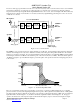
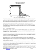
AMBE-2000™ Vocoder Chip User’s Manual Version 4.9 In order to ensure proper performance from the voice coder, it is necessary for the vocoder front end to meet a set of minimum performance requirements. For the purposes of this section the vocoder front end is considered to be the total combined response between microphone/speaker and the digital PCM interface to the vocoder, as shown in Figure 2-B.
AMBE-2000™ Vocoder Chip User’s Manual Version 4.9 +2 dB -1 dB -2 dB -18 dB -40 dB -60 dB 0 200 3000 3400 4000 Figure 2 - D. 4600 8000 freq (Hz) Front End Output Filter Mask This document assumes that the A-to-D converter produces digital samples where the maximum digital input level (+3 dBm0) is defined to be +/- 32767, and similarly, that the maximum digital output level of the D-to-A converter occurs at the same digital level of +/- 32767.
AMBE-2000™ Vocoder Chip User’s Manual Version 4.9 synchronization with the data stream before it can properly synthesize the speech waveform. The Unframed mode only commits a single bit per frame to maintain data alignment. In higher error rate channels the performance will be improved by adding more bits per frame to the alignment information (which is more easily performed when using Framed mode).
AMBE-2000™ Vocoder Chip User’s Manual Version 4.9 3 Hardware Information 3.1 Special Handling Instructions The AMBE-2000™ uses the TM320LC541B-66 core. For more details on handling, electrical characteristics, packaging, or timing constraints please refer to the TMS320-C54x manual found at http://www-s.ti.com/sc/psheets/sprs039c/sprs039c.pdf (Adobe Acrobat).
AMBE-2000™ Vocoder Chip User’s Manual Version 4.9 3.2 Pin Descriptions Pin Number Pin Descriptive Name Pin Direction Notes 77 CHAN_SEL1 Input Channel Interface Selection Pins: Use these bits to select the channel interface type (framed, unframed, active and passive) according to Table 4-A. See full description in section 4.2.
AMBE-2000™ Vocoder Chip User’s Manual Version 4.9 41 CODEC_TX_DATA Output PCM Data from AMBE-2000™ to D/A Converter 27 CODEC_RX_CLK Input 33 CODEC_TX_CLK Input D/A Serial clock Should be connected to CODEC_RX_CLK A/D Serial clock. Should be connected to CODEC_TX_CLK 51 CLOCK_MODE Input If high enables crystal oscillator option for clock source. If low then external oscillator option is selected. See Section 3.5 for details.
AMBE-2000™ Vocoder Chip User’s Manual Version 4.9 3.3 Clock and Reset Timing To reset the AMBE-2000 chip, the reset signal must be held low for a minimum of 50 µs. The recovery time from reset is approximately 95 ms. In other words, 95 ms after the rising edge of the reset signal the AMBE-2000™ starts processing PCM samples. The first packet will be ready after 252 PCM samples are read.
AMBE-2000™ Vocoder Chip User’s Manual Version 4.
AMBE-2000™ Vocoder Chip User’s Manual Version 4.9 3.4 Associated Chip Delay The associated delay due to the coding/decoding algorithm is shown below Encoder Delay Algorithmic Delay = 32 ms Encoder Processing Delay = 11.5 ms Decoder Delay Algorithmic Delay = 10 ms Decoder Processing Delay = 7.5 ms Total Delay = 32 ms + 11.5 ms + 1 ms* +10 ms +7.5 ms = 62 ms Frame Processing Delay = 11.5 ms (encoder) + 1 ms* + 7.5 ms = 20 ms * 1ms of idle time between encode and decode sequence. 3.
AMBE-2000™ Vocoder Chip User’s Manual Version 4.9 Figure 3-D X2/CLKIN and X1 with Crystal Oscillator C1 = 10 pF X2/CLKIN (pin 68) 16.384 MHz AMBE-2000 X1 (pin 67) C2 = 10 pF DVSI Confidential Proprietary, Subject to Change Visit us at www.dvsinc.
AMBE-2000™ Vocoder Chip User’s Manual Version 4.9 3.6 Package Description 100 pin TQFP (Thin Quad Flat Pack) All Dimensions are in millimeters Figure 3-E Package Dimensions 16.20 / 15.80 SQ 14.20 / 13.80 SQ 12.00 TYP 75 51 76 50 100 26 25 1.40/1.60 mm 1 o 12 All Around 0.5 mm Detail 0.17 / 0.27 Gage Plane 0.13NOM 1.35 /1.45 1.60 MAX 0.05 0 - 7 MAX 0.25 0.45 / 0.75 Not Drawn to Scale Figure 3-F AMBE-2000 Chip Markings DVSI Confidential Proprietary, Subject to Change Visit us at www.
AMBE-2000™ Vocoder Chip User’s Manual Version 4.9 AMBE-2000-10 = The DVSI device part number. DVSI = Digital Voice Systems, Incorporated D16876PZ-66 = Internal Texas Instruments part number for the AMBE-2000 A = WF Code D = Die Rev Code W = Die Shrink Code 43AT3FW = Lot Trace Code 43 = 2 Digit YR/MO Code (Updated Monthly) AT3F = Assy Lot W = Assy Site Code 3.7 Normal Operating Conditions Table 3-C Normal Operating Conditions Normal Operating Conditions 3.8 Operating Voltage 3.
AMBE-2000™ Vocoder Chip User’s Manual Version 4.9 Table 3-D Absolute Maximum Ratings Absolute Maximum Ratings Voltage Range on any Pin with Respect to Ground 3.9 -0.3V to 4.6V Electrical Characteristics and Requirements Table 3-E Recommended Operating Conditions Parameter Min Nom Max Unit DVDD Device Supply Voltage 3 3.3 3.6 V VSS Supply Voltage, GND - 0 - V - DVDD + 0.
AMBE-2000™ Vocoder Chip User’s Manual Version 4.9 4 4.1 Channel Interface Overview The Channel Interface is the general term used for the interface for the compressed bits coming from the encoder and the compressed bits going to the decoder. This same interface is also used to output status information from the encoder and decoder such as whether a DTMF tone has just been detected in the speech input, or whether the decoder has detected and synthesized a frame of silence.
AMBE-2000™ Vocoder Chip User’s Manual Version 4.9 4.2 Serial Configuration Selection The hardware interface to the Channel Interface is configured as a serial interface based exclusively on the hardware settings of CHAN_SEL [1-0]. See Table 4-A.
AMBE-2000™ Vocoder Chip User’s Manual Version 4.9 4.3 Channel Serial Mode The signals in Table 4-C make up the serial channel interface. The serial channel mode transfers data in and out of the AMBE-2000™ using 16 bit words on the two data lines CHAN_RX_DATA and CHAN_TX_DATA. The selection of the framed or unframed format of this data is made using information in Table 4-A.
AMBE-2000™ Vocoder Chip User’s Manual Version 4.9 4.3.
AMBE-2000™ Vocoder Chip User’s Manual Version 4.9 Table 4-E Switching Characteristics Over Recommended Operating Conditions for Serial Port Receive Reference td(SCK) tc(SCK) tf(SCK) tr(SCK) tw(SCK) tsu(FSR) tsu(DR) td(FSX) td(DX) th(FSX) th(FSX)H tdis(DX) th(DX) Parameter Delay time, DX valid after CLKX rising (Passive Mode) Cycle time, serial port clock 3.
AMBE-2000™ Vocoder Chip User’s Manual Version 4.9 5 Channel Data Format The channel interface is responsible for outputting the compressed data from the encoder and inputting compressed data to the decoder. In addition to these most basic functions the channel interface is also capable of reporting certain events, such as the detection of a DTMF tone. The channel interface can also control certain selectable functions of the AMBE-2000™, such as the voice coding rate.
AMBE-2000™ Vocoder Chip User’s Manual Version 4.9 5.2.1 Framed Input: Word 0 : Header The decoder uses the header information to synchronize with the beginning of each 20 millisecond frame. This 16-bit word MUST be 0x13EC. 5.2.2 Framed Input: Word 1 : Power Control ID Set the 8-bit Power Control ID field to 0x00 for normal use. For Power Down Mode, set this value to 0x55. This causes the AMBE-2000™ to enter low power mode. To exit low power mode, the device must be reset through the hardware.
AMBE-2000™ Vocoder Chip User’s Manual Version 4.
AMBE-2000™ Vocoder Chip User’s Manual Version 4.9 5.2.8 Framed Input: Word 10 : DTMF Control Use this word to set DTMF tones. See Table 5-F for a list of tones and their corresponding values. . An expanded list of tones and values can be found in the Appendices, Section 8.4.
AMBE-2000™ Vocoder Chip User’s Manual Version 4.9 5.2.9 Framed Input: Word 11 : Control Word 2 Table 5-G Control Word 2 Format Control Word 2 – 16-bits Bit 15 14 13 12 11 10 9 Decoder Output Volume Control 8 7 6 Unused 0 Unused 0 5 4 3 2 VAD Unused 0 SL EC 1 0 RIS Decoder output volume control The default gain value is set to 0x80h Rate Information Selector (RIS): Use these 2 bits to select which part(s) of the vocoder will be affected by the rate selection words.
AMBE-2000™ Vocoder Chip User’s Manual Version 4.9 5.3 Framed Output The format for Framed output data is shown in Figure 5-B. Only the bits in the Channel Data Bits are transmitted along with framing information (data used to locate the start of each frame for proper reconstruction at the decoder) over the channel. The first 192 bits provide overhead information, which is sometimes useful to the host but is generally not transmitted over the channel. Figure 5-B Basic Framed Output 5.3.
AMBE-2000™ Vocoder Chip User’s Manual Version 4.9 Decoder Silence Detect: When the Decoder Silence Detect flag is set to 1, the decoder is reporting that the last frame decoded was a comfort noise frame. Encoder DTMF Detect: The Encoder DTMF Detected Flag will be set to a 1 when the encoder detects a DTMF tone. Encoder Silence Detect: The Encoder Silence Detected Flag will be set to 1 when no voice activity is detected.
AMBE-2000™ Vocoder Chip User’s Manual Version 4.9 5.3.8 Framed Output: Word 10 : DTMF Control This word corresponds to the DTMF Detection capabilities of the vocoder. It uniquely identifies specific tones recognized by the encoder. See table 5-M for a list of tones and their corresponding values.
AMBE-2000™ Vocoder Chip User’s Manual Version 4.
AMBE-2000™ Vocoder Chip User’s Manual Version 4.9 Sleep (SL): A 1 in this field indicates the device has been put into sleep mode. Decoder Output Volume Control: Indicates the current decoder volume. 5.3.10 Framed Output: Words 12-23 : Channel Data This is the field that contains the actual coded bits. Output of the data begins with the MSB of the first word in this field and continues through with the final bit output being the LSB of the final word.
AMBE-2000™ Vocoder Chip User’s Manual Version 4.9 transferred into the decoder for each 20-millisecond frame will be the number of bits per frame divided by the number of bits per word. So a system coding at 4800 bps with 3 bits per word will need to write exactly 32 ([4800 ÷50] ÷3 = 32) words each frame.
AMBE-2000™ Vocoder Chip User’s Manual Version 4.9 6 6.1 A/D-D-A Interface A/D-D/A Overview The interface from the analog world of speech to the AMBE-2000™ is typically an A/D-D/A chip. Selection of the A/D-D/A chip should be made carefully, with a preference given to 16 bit linear devices. Additionally, consideration should be given for signal to noise ratios and filtering characteristics typically built into many such devices.
AMBE-2000™ Vocoder Chip User’s Manual Version 4.9 6.
AMBE-2000™ Vocoder Chip User’s Manual Version 4.9 Table 6-E Switching Characteristics Over Recommended Operating Conditions for Serial Port Receive Reference td(SCK) tc(SCK) tf(SCK) tr(SCK) tw(SCK) tsu(FSR) tsu(DR) td(FSX) th(FSX) th(FSX)H tdis(DX) th(DX) Delay time, DX valid after CLKX rising 3.
AMBE-2000™ Vocoder Chip User’s Manual Version 4.9 7 7.1 Special Functions Hardware vs. Software Selection Note Many of the functions of the AMBE-2000™ can be accessed through both hardware and software interfaces to the device. The following hardware inputs, CHANN_SEL [1-0], RATE_SEL [4-0], CODEC_SEL [1-0], VAD_EN, ECHOCAN_EN, and SLEEP_EN, are only accessed for input during the first 200 microseconds after a hardware reset on RESETN.
AMBE-2000™ Vocoder Chip User’s Manual Version 4.
7.4 AMBE-2000™ Vocoder Chip User’s Manual Version 4.9 Voice Activation Detection (VAD), Comfort Noise Insertion (CNI) The Voice Activation Detection (VAD) algorithm along with the Comfort Noise Insertion (CNI) feature of the AMBE-2000™ chip performs useful functions in systems trying to convert periods of silence, that exist in normal conversation, to savings in system bandwidth or power. With the VAD functions enabled, periods of silence will be denoted by the encoder in two ways.
AMBE-2000™ Vocoder Chip User’s Manual Version 4.9 7.6.2 Power Down Power Down provides the lowest power usage of the sleep modes, the only drawback to this mode is the necessity of a hardware reset on RESETN (pin 69) to resume normal operation. Table 7-C Summary of Power Saving Modes Power Consumption Sleep Mode Enter State via Return to Normal Operation via Wake Up Time 3V CMOS TTL Crystal Approx.
AMBE-2000™ Vocoder Chip User’s Manual Version 4.9 7.7 Slip Enable In any real time communication system, clock skew issues must be anticipated to keep the flow of data smooth from one end of the system to the other. The SLIP_EN (pin 82) signal allows the encoder of the AMBE-2000™ to react to small slips in the encoder channel signals. When the AMBE-2000™ is in active mode, the chip produces the signals internally for the transfer of data.
AMBE-2000™ Vocoder Chip User’s Manual Version 4.
AMBE-2000™ Vocoder Chip User’s Manual Version 4.9 For example with an Average-Frame-Interval = .02 (i.e. 20 ms) and a Sample-Rate = 8000, then with 100 parts per million oscillator accuracy (i.e. Frame-Drift = Sample-Drift = .0001), then above constraint equates to 4 < N < 31.25, and N=30 would be a reasonable selection. In this case the system would input the specified Slip Control Packet into the AMBE-20X0 vocoder chip every 30’th frame enabling the vocoder chip to adjust for the actual clock drift.
AMBE-2000™ Vocoder Chip User’s Manual Version 4.9 DVSI Confidential Proprietary, Subject to Change Visit us at www.dvsinc.
AMBE-2000™ Vocoder Chip User’s Manual Version 4.9 8 Appendices 8.1 Example A/D-D/A Usage The following examples of A/D-D/A chips have been included to show connections necessary for interfacing to a number of popular chips. U1 CODEC_RX_CLK CODEC_TX_CLK CODEC_TX_STRB CODEC_RX_STRB CODEC_RX_DATA CODEC_TX_DATA 27 U2 33 14 37 17 29 18 31 16 41 19 SCLK SE SDOFS MCLK SDIFS AVDD1 SDO AVDD2 SDI DVDD 20 15 SERIAL PORT ENABLE (HIGH) 16.384 MHz 3 9 5V 12 3.
AMBE-2000™ Vocoder Chip User’s Manual Version 4.9 8.2 Example: Texas Instruments TLV320AIC10 Usage The Texas Instruments’ TLV320AIC10 codec presents a simple low cost solution for use with DVSI’s AMBE-2000™ vocoder chip. This application note provides information on interfacing these components. Figure 1 shows a sample block diagram interface, between the TLV320AIC10 codec and DVSI’s AMBE-2000™ vocoder chip.
AMBE-2000™ Vocoder Chip User’s Manual Version 4.9 The logic connected to the DCSI port does not have to be disabled. The user can make adjustments to the configuration as needed (for example ADC and DAC gain). A reset to the TLV320AIC10 codec will reset all of the internal registers. As a result, the TLV320AIC10 must be reconfigured following a reset.
AMBE-2000™ Vocoder Chip User’s Manual Version 4.9 VDD SHIFT D_IN [15:0] CNTL_DATA [15:0] AIC_CTRL Serial Out LOAD AIC_LOAD LS_IN CLK_EN SCLK CLK COUNT U5A 1 2 1 U6A 2 Q0 Q1 2 3 U9 1 1 U8A 2 4 5 AIC_LOAD AND4 Q2 U7A CE Q3 1 2 CLK CLR Figure 3: TLV320AIC10 Codec Configuration Detail Reference Materials: AMBE-2000™ Vocoder chips Users Manual: http://www.dvsinc.com/literature.htm TLV320AIC10 Data Sheet: http://www-s.ti.com/sc/ds/tlv320aic10.
AMBE-2000™ Vocoder Chip User’s Manual Version 4.9 TLV320AIC10 Reference Schematic (Analog Section) C1 820pF R1 10K VOICEOUTP R3 100K 7 C2 10uF + R2 20K 3.3VA 3.3VA + 5 - 6 U1B R4 100K U1A AD8544 R5 10K 4 1 C4 2 nF C3 200pF + 3 - 2 R6 20K VOICEOUTM 11 3.3VA R7 220 R8 R9 10K J1 2 3 1 4 10K 2 3 1 4 + R10 10K C5 10uF Handset AURXM C6 0.1uF R11 10K R12 220K AURXFP + 3VA R13 5.6K C7 10uF R15 10K VMID R14 4.
AMBE-2000™ Vocoder Chip User’s Manual Version 4.9 8.3 Configuring the AD73311 for 3-Volt Operation The Analog Devices AD73311 codec chip presents a simple low cost solution for use with DVSI’s AMBE-2000™ Vocoder chip. This application note provides information on alternative methods of interfacing these components. AD73311 Codec (using a 3 volt supply) It may be desirable for the AD73311 AD/DA converter to be configured for a 3-volt supply voltage instead of a 5-volt supply voltage.
AMBE-2000™ Vocoder Chip User’s Manual Version 4.
AMBE-2000™ Vocoder Chip User’s Manual Version 4.9 AD73311 - Data Sheet http://www.analog.com/productSelection/pdf/AD73311_b.pdf AD73311L - Data Sheet http://www.analog.com/productSelection/pdf/AD73311L_a.pdf DVSI Confidential Proprietary, Subject to Change Visit us at www.dvsinc.
AMBE-2000™ Vocoder Chip User’s Manual Version 4.9 8.4 Interfacing to the Texas Instruments PCM3500 Codec The Texas Instruments PCM3500 codec chip presents a simple low cost solution for use with DVSI’s AMBE-2000™ or AMBE-2020™ vocoder chips. This application note provides information on alternative methods of interfacing these components. PCM3500 The block diagram in Figure 1 shows a sample interface between the PCM3500 codec and DVSI’s AMBE-2000™ vocoder chip.
C1 47nF 3.3VA 1 C2 2.2uF R1 20K 4 1 C4 10uF + + 3 - 2 R2 2.1K 2 R3 887 U2 1 2 C3 4.7uF 11 U1A C7 100nF C6 1nF 1 2 1 2 C5 4.7uF Analog In R4 220 4 5 J1 3.3 V 2 3 1 4 3 2 3 1 4 6 7 R5 220K CODEC_TX/RX_CLK 2 1 8 CODEC_TX/RX_STRB 9 Handset C10 0.2uF U1B 3.3VA R6 10K 10 CODEC_RX_DATA 11 12 6 5 + 7 3.3VA Vcc Vref1 AGND Vref2 Vout Vin AGND AGND /PDWN M/S Loop TSC HPFD BCK XTI FS XT0 DIN DOUT FSO SCKIO DGND Vdd PCM3500 24 3.
Application Information It is strongly recommended that the user review the Application Information provided in the Texas Instruments PCM3500 data sheet before finalizing any design. Additional Reference Material AMBE-2000™ or AMBE-2020™ vocoder chip Users Manual http://www.dvsinc.com/literature.htm Application Report – Understanding Data Converters: http://www-s.ti.com/sc/psheets/slaa013/slaa013.pdf PCM3500 Data Sheet http://www-s.ti.com/sc/ds/pcm3500.pdf PCM3500 Evaluation Board http://www-s.ti.
AMBE-2000™ Vocoder Chip User’s Manual Version 4.9 8.5 Expanded Tone Detection and Generation The AMBE-2000™ is capable of detecting and generating single tones as well as dual tones. The single tones span from 156.25 Hz to 3812.5 Hz in 31.25 Hz steps. 8.6 Tone Index (Decimal) Tone Type Freq #2 (Hz) Freq #1 (Hz) 0-4 Invalid N/A N/A 5 Single N/A 156.25 6 Single N/A 187.5 7 Single N/A 218.75 ……… …………. ………… …………… 122 Single N/A 3812.
AMBE-2000™ Vocoder Chip User’s Manual Version 4.9 1111 Most confident 1 Placing a logic high on pin 79 of either the AMBE-2000™ or AMBE-2020™ vocoder chips enables the soft decision error correction on the decoder. Enabling the soft-decision does nothing to the encoder packet. The packet will look like a normal encoded packet.
AMBE-2000™ Vocoder Chip User’s Manual Version 4.9 Table 1.
8.7 AMBE-2000™ Vocoder Chip User’s Manual Version 4.9 Special Rate 2350 bps Voice / 50 bps FEC AMBE-1000™ Vocoder Chip Compatible Mode The following procedure is for implementing the AMBE-2000/2020™ in a special mode that is compatible to AMBE-1000™ Vocoder Chip at 2350 bps voice and 50 bps FEC. This procedure is ONLY required when interoperating with the AMBE-1000™ Vocoder Chip at this specific rate (2350 voice + 50 bps FEC).
AMBE-2000™ Vocoder Chip User’s Manual Version 4.9 Compatible Mode Procedure Step 2. The next packet should be identical to the packet described in Table 3. Special Control Packet Word # 0 1 2 3 4 5 6 7 8 9 10 11 12-23 Table 3.
AMBE-2000™ Vocoder Chip User’s Manual Version 4.9 History of Revisions Revision Number Date of Revision Description 1.0 November 1999 Initial Version April 2000 Pin descriptions Serial Configuration Selection Channel Serial Interface Pin Descriptions 11-12 19 20 Table 6-A CODEC_SEL[1-0]: A/D- D/A Hardware Configuration Values 35 1.1 Pages 1.2 May 2000 Deleted the word parallel Table 5-N Control Word Format: Removed VAD in bit 5. This is not used as an output. 1.
AMBE-2000™ Vocoder Chip User’s Manual Version 4.9 History of Revisions Revision Number Date of Revision Description Pages 4.0 January 2003 Various Grammer Changes Vad Threshold Explination Associated Delay Front End Requirements Added AD73311AR Configuration Words Change to Echo Cancellor Description Added Tech Note 8.2 Expanded DTMF Tone Chart Soft Decision White Paper Added BER Information TLV320AIC10 Application Note.