
User`s manual

AMBE-2000™ Vocoder Chip
User’s Manual Version 4.9
DVSI Confidential Proprietary, Subject to Change Page 13
Visit us at www.dvsinc.com
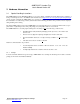
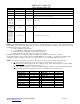
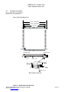
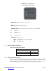
3.2 Pin Descriptions
Pin Number Pin Descriptive Name Pin Direction Notes
77 CHAN_SEL1 Input Channel Interface Selection Pins: Use these bits to select the channel interface type
(framed, unframed, active and passive) according to Table 4-A. See full description in
section 4.2.
75 CHAN_SEL0 Input Used with CHAN_SEL1 to select channel operation mode
85 CODEC_SEL1 Input
84 CODEC_SEL0 Input
A/D-D/A Select Pins see Table 6-A to select the interface.
74 RATE_SEL4 Input
73 RATE_SEL3 Input
72 RATE_SEL2 Input
71 RATE_SEL1 Input
70 RATE_SEL0 Input
Coding Rate Select Pins: Use these bits to select the voice and FEC rates according to
section 7.2. The coding rates are also selectable using the Control Word interface
described in section 5.2.4.
86 VAD_EN Input
Voice Activation Detection Enable Pin. Active HIGH. See Section 7.4. VAD can also be
enabled/disabled using the Control Word interface as described in section 5.2.9.
78 ECHOCAN_EN Input
Echo Canceller Enable Pin. Active HIGH. See Section 7.3. The Echo Canceller can also
be enabled/disabled using the Control Word interface as described in section 5.2.9.
83 SLEEP_EN Input Standard Sleep Enable Pin. Active HIGH. See Section 7.6.1.
82 SLIP_EN Input Slip Control Enable Pin. Active HIGH. See Section 7.7.
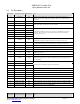
68 X2/CLKIN Input Clock Input 1. 16.384 Mhz input. See Section 3.3
67 X1 Input
Output from internal oscillator for the crystal. If the internal oscillator is not used this pin
should be unconnected.
69 RESETN Input AMBE-2000™ Reset pin. Active LOW. See Section 3.3
20 EPR Output
Encode Packet Ready: Following a reset, this signal will have a high to low transition to
indicate the first packet is ready. The next packet will be ready approximately 20 msec
later. See Note 1.
79 SOFT_EN Input Soft decision decoding enable. Enables 4 bit soft decision error decoder.
80 BAUD_SEL0 Input
81 BAUD_SEL1 Input
Baud Rate Selector for unframed serial mode See Table 4-B.
32 CHAN_RX_DATA Input Channel Receive Data to AMBE-2000™
42 CHAN_TX_DATA Output Channel Transmit Data from AMBE-2000™
28 CHAN_RX_CLK Input Channel Receive Clock
34 CHAN_TX_CLK Input Channel Transmit Clock
38 CHAN_TX_STRB I/O Channel Transmit Data Strobe
30 CHAN_RX_STRB Input Channel Receive Data Strobe
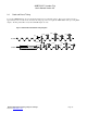
29 CODEC_RX_STRB Input Frame synchronization pulse for A/D data. Should be connected to CODEC_TX_STRB
37 CODEC_TX_STRB Input Frame synchronization pulse for D/A data. Should be connected to CODEC_RX_STRB
31 CODEC_RX_DATA Input PCM Data from A/D Converter to AMBE-2000™
Pin Number Pin Descriptive Name Pin Direction Notes