FA100-00107 BOARD MANUAL FAA20 Embedded NEXCOM Vocoder Board Manual Document Version 1.0.0 March 2004 Prepared For: Federal Aviation Administration William J. Hughes Technical Center Atlantic City International Airport, NJ 08405 Prepared By: CIE Engineering, Inc. 600 Maryland Avenue, S.W., Suite 740 Washington, DC 20024 www.cie-eng.com (202) 484-2298 This document has been prepared by CIE under contract with the Federal Aviation Administration.
FAA20 Embedded NEXCOM Vocoder Board Manual Table of Contents 1.0 1.1 1.2 1.3 1.4 2.0 2.1 2.2 3.0 3.1 3.2 3.3 3.4 3.5 4.0 INTRODUCTION.................................................................................................................... 1 Purpose and Scope ........................................................................................................1 References .......................................................................................................................
FAA20 Embedded NEXCOM Vocoder Board Manual 5.3.7 Voice Activity/Peak Detectors .............................................................................27 5.4 System Timing and Control .........................................................................................28 5.4.1 Truncated Timing Mode .......................................................................................28 5.4.2 Voice Delay ..............................................................................................
FAA20 Embedded NEXCOM Vocoder Board Manual 8.3.12 8.3.13 8.3.14 8.3.15 8.3.16 8.3.17 8.3.18 8.3.19 8.3.20 8.3.21 8.3.22 8.3.23 8.3.24 8.3.25 8.3.26 8.3.27 8.3.28 8.3.29 8.3.30 8.3.31 8.3.32 8.3.33 8.3.34 8.3.35 9.0 DELAY.....................................................................................................................77 DM ...........................................................................................................................78 DUMP ....................................
FAA20 Embedded NEXCOM Vocoder Board Manual List of Figures Figure 1: FAA20 Vocoder Board ...................................................................................................... 3 Figure 2: DIN 41612 Connector Diagram......................................................................................... 5 Figure 3: DB9F Connector Diagram ................................................................................................. 9 Figure 4: VC20 Forced Configuration Items..............
FAA20 Embedded NEXCOM Vocoder Board Manual Table 11: Table 12: Table 13: Table 14: Table 15: Table 16: Table 17: Table 18: Table 19: Table 20: Table 21: Table 22: Table 23: Table 24: Table 25: Table 26: Table 27: Table 28: Table 29: Table 30: Table 31: Table 32: Table 33: Table 34: Table 35: Table 36: Table 37: Table 38: Table 39: Table 40: Table 41: Table 42: Table 43: Table 44: Table 45: Table 46: Table 47: ADAPT Command Syntax.............................................................................
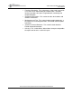
FAA20 Embedded NEXCOM Vocoder Board Manual 1.0 INTRODUCTION This document provides the information needed to integrate and operate the FAA20 embedded NEXCOM vocoder. 1.1 Purpose and Scope This document serves the following purpose: • Describes FAA20 integration and operation This manual covers hardware revision B. While the FAA20 software is designed to run on both platforms (revision A and revision B), there are minor differences in control bits and interfaces.
FAA20 Embedded NEXCOM Vocoder Board Manual • • • • • Functional Description. This section covers various topics to provide users with a basic understanding of FAA20 function. It includes interface operation, voice processing flow details, and timing and control information. Architectural Description. This section describes the hardware and software architectures. Maintenance and Test.
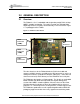
FAA20 Embedded NEXCOM Vocoder Board Manual 2.0 GENERAL DESCRIPTION 2.1 Overview The FAA20 is a 4” x 5” embedded card designed to provide DVSI 4.8 kbps AMBE+ Vocoder functionality. The card is based on the TMS320C5416 Digital Signal Processor (DSP) manufactured by Texas Instrument. Figure 1 is a photograph of the FAA20.
FAA20 Embedded NEXCOM Vocoder Board Manual 2.
FAA20 Embedded NEXCOM Vocoder Board Manual 3.0 CONNECTORS, CONTROLS, AND INDICATORS This section provides detailed information on the FAA20 connectors, controls and indicators. The following topics are included: • • • • • Main Signal Connector. Provides signal pinouts and descriptions for the DIN 41612 connector (96 pins). Terminal Connectors. Provides signal pinouts and descriptions for the DB9F connectors (9 pins – 2 each). Audio Connectors.
FAA20 Embedded NEXCOM Vocoder Board Manual Table 1: DIN Signals SIGNAL PIN NIBBLE SIGNALS ENC3 C4 ENC2 C15 ENC1 C16 ENC0 A4 DIR DESCRIPTION O Encoder Data: The compressed voice data is proved as a sequence of nibbles from the ATC-10B encoder. A total of 25 nibbles is provided every vocoder frame. The first nibble is a control nibble that is nominally set to 0000 (binary). The subsequent 24 nibbles contain the 96-bit encoded voice data packet. Each nibble is output on the rising edge of ENCCK.
FAA20 Embedded NEXCOM Vocoder Board Manual SIGNAL PIN DIR DESCRIPTION DR B11 I SCLK B9 I/O FSX B7 I/O FSR B12 I/O SPRDY C7 O Serial Receive Data: Linear 16-bit PCM voice is input to the FAA20 at a rate of 8000 samples/second. Each sample is received serially (MSB first) beginning with the falling edge of the SCLK after the FSR signal is detected. Serial Shift Clock: The serial shift clock transfers transmit and receive serial data. Transmit data is output on the rising edge of clock.
FAA20 Embedded NEXCOM Vocoder Board Manual SIGNAL PIN DIR DESCRIPTION DDAT A21 O rsvd GO C24 I TMTX B32 O TMRX B31 I DTMF Data Output (active high): This signal is not used by the FAA20. During power up, it is initialized to the low (inactive) state. GO Mode (active high): The GO signal must be active to place the encoder in voice mode. The FAA20 samples this signal on the falling edge of DCLK when the DFS bit is also set.
FAA20 Embedded NEXCOM Vocoder Board Manual 3.2 Terminal Connectors The two DB9F serial connectors are used for terminal control. The connectors labeled UART A and UART B on the silkscreen are the COM1 and COM2 interfaces, respectively. Both/either interface can be used for terminal control and software download with one exception. If the main program is erased and the unit is power cycled, the boot application only uses COM1. The boot application supports main program download.
FAA20 Embedded NEXCOM Vocoder Board Manual 3.3 Audio Connectors The two 1/8” stereo jacks provide access to the analog audio interface. The FAA20 only supports a single analog interface, i.e. these jack signals are wired in common with the associated DIN connector signals. Although the internal audio amplifier can drive 8-ohm speakers, the interface is compatible with 600-ohm audio interfaces.
FAA20 Embedded NEXCOM Vocoder Board Manual 3.4 LED Indicators Table 4 describes the default LED indicator assignments. The FAA20 supports programmable functions for the LEDs. For more information on LED assignment, see Section 5.4.3. Table 4: LED Indicators* LED ASSIGNMENT DESCRIPTION LED1 (red) LED2 (yellow) LED3 (green) LED4 (red) LANYP LED5 (yellow) VAD LED6 (green) RUN Audio Peak Indicator. Lights when audio signal level reaches the peak threshold, i.e. +3 dBm0. Audio Activity Indicator.
FAA20 Embedded NEXCOM Vocoder Board Manual 3.5 Switch Controls Table 5 describes the function of FAA20 switches. These switches are read only during power up. Table 5: Switch Controls SWITCH SW1 FUNCTION PCM_MASTER SW2 NIB_MASTER SW3 ADAPT_EN SW4 TRUNC_EN SW5 PCM_SELECT SW6 SW7 SW8 Reserved OPMODE DESCRIPTION PCM Master Timing. When ON, the FAA20 generates PCM timing. When OFF, the external device generates PCM timing. Nibble Master Timing. When ON, the FAA20 generates nibble interface timing.
FAA20 Embedded NEXCOM Vocoder Board Manual 4.0 INSTALLATION This section provides FAA20 installation instructions. The following topics are included: • • • Connecting to the FAA20. Provides guidance for board integration. Setting up Switch Controls. Provides guidance for configuring the on-board switches. Setting up Flash Configuration Parameters. Provides guidance for configuring other FAA20 parameters stored in flash memory.
FAA20 Embedded NEXCOM Vocoder Board Manual 3. Select the proper adapter configuration (SW3). This switch setting is important for configurations that use the PCM interface. If the host system can support both the 8 ksps and 6.67 ksps digital frame rates, set SW3=OFF. If on the other hand, the host system only supports the standard 8 ksps voice sample rate, enable the adapter, i.e. set SW3=ON. 4. Select the truncated timing switch (SW4) to the OFF position.
FAA20 Embedded NEXCOM Vocoder Board Manual • • voice should be 20 ms and 24 ms, respectively. The nominal nibble clock rates are 9600 and 8000 Hz, respectively, for normal and truncated timing modes. For a special framing nibble framing mode that supports truncated timing at the 9600 Hz rate, see Section 5.2.3 Clock Reference (CLKREF). The CLKREF parameter is used to control the internal linear voice processing task.
FAA20 Embedded NEXCOM Vocoder Board Manual modes, the flow (MIX & ROUTE) is NOT loaded from flash, but is set to a known, fixed configuration. For the VC20 mode, however, the active linear power can be selected with SW5. In addition to the GAM and MIX level commands, there are LED status indicators that provide an coarse measure of signal level. • LANYP and LANYA LED Indicators. The audio should cause the LANYA indicator to light and should NOT cause the LANYP peak indicator to light.
FAA20 Embedded NEXCOM Vocoder Board Manual 5.0 FUNCTIONAL DESCRIPTION This section provides a functional overview of the FAA20. The following topics are included: • • • • 5.1 Operational Modes. Discusses the normal operational mode and three other optional modes. Interfaces. Discusses details for each of the three external voice port types: the audio interface, the digital PCM interface and the nibble interface. Interface timing diagrams are provided. Voice Processing.
FAA20 Embedded NEXCOM Vocoder Board Manual Figure 4: VC20 Forced Configuration Items VC20 Fixed Configuration Items (SW5=OFF) > > > > > > > > > > > ADAPT = OFF FRAMESIZE NIB NORM = 192 FRAMESIZE NIB TRUN = 192 MIX AUD <- VOC (0x7FFF) MIX PCM -- OFF MIX VOC <- AUD (0x7FFF) MIX COM -- OFF MIX TON -- OFF ROUTE VOC <- NIB ROUTE NIB <- VOC ROUTE COM <- COM VC20 Fixed Configuration Items (SW5=ON) > > > > > > > > > > > ADAPT = OFF FRAMESIZE NIB NORM = 192 FRAMESIZE NIB TRUN = 192 MIX AUD -- OFF MIX PCM <- VO
FAA20 Embedded NEXCOM Vocoder Board Manual 5.1.4 TEST Mode The TEST mode supports FAA20 integration testing. It is especially designed to allow back-to-back FAA20 unit connection (requires adapter board). In this mode, the most of the automatic external vocoder controls are disabled to allow manual control of these items. Specifically, the following vocoder signal conductors are ignored: VAD, GO, TMRX. 5.2 Interfaces 5.2.
FAA20 Embedded NEXCOM Vocoder Board Manual FAA20 has no such restriction. The SPRDY signal is internally pulled high with a pull-up resistor. Although the figure shows alignment of the FSX and FSR signals, this is not a requirement. The maximum SCLK rate is 4.096 MHz. The PCM clock rate can be changed “on-the-fly” to support switching between normal and truncated timing modes; however, the transition should be glitch-free. 5.2.
FAA20 Embedded NEXCOM Vocoder Board Manual The FAA20 nibble signaling requirements are identical the VC20 nibble signaling requirements. Figure 8 provides signal timing information.
FAA20 Embedded NEXCOM Vocoder Board Manual 5.3 Voice Processing The FAA20 voice processing flow includes the following major functional blocks: • • • • • • • AMBE+ Vocoder Linear Voice Mixer Packet Voice Router PCM Rate Adapter Tone Generator Gain, Attenuation, and Mute (GAM) Voice Peak/Activity Detectors Figure 9 is a voice processing flow diagram. The diagram is divided into two major areas: linear audio and compressed audio. The AMBE+ vocoder is positioned between these two areas. 5.3.
FAA20 Embedded NEXCOM Vocoder Board Manual The FAA20 software actively controls the parameters listed in the VOC command. This active control is disabled when TEST BITEXACT mode is enabled. This allows the test vectors supplied at the serial ports to control the vocoder, as required. For test vector support, see Section 7.4.
FAA20 Embedded NEXCOM Vocoder Board Manual 5.3.2 Linear Voice Mixer The linear voice mixer controls the flow of linear voice through the FAA20. The mixer has five ports: the analog audio port (AUD), the digital PCM port (PCM), the vocoder port (VOC), the tone generator port (TON), and the external communication port (COM). The mixer supports weighted signal summing with saturation control.
FAA20 Embedded NEXCOM Vocoder Board Manual 5.3.3 Packet Voice Router The packet voice router controls the flow of compressed voice packets through the FAA20. The router has three ports: the vocoder port (VOC), the nibble port (NIB), and the external communication port (COM). Figure 11: Packet Voice Router VOC Port Selector VOC NIB NIB COM COM Port Port PACKET VOICE ROUTER Unlike the mixer, each output port can be connected to one and only one input port.
FAA20 Embedded NEXCOM Vocoder Board Manual for compressed voice, a rate factor of 5/6 is required. Two filters are required. The receive filter down-converts the 8 ksps to 6.67 ksps before sending the data to the encoder. The transmit filter up-converts the 6.67 ksps decoded voice to 8 ksps before sending the data to the PCM output port. Figure 12 provides a block diagram for the PCM rate adapter. Figure 12: Rate Adapter Block Diagram 8 ksps L=5 é 40 ksps Low Pass Filter N = 120 6.
FAA20 Embedded NEXCOM Vocoder Board Manual Figure 13: Low Pass Filter Characteristics -20 dB @ 3333 Hz 5 dB/division 5.3.6 Gain, Attenuation, Mute (GAM) The gain, attenuation, and mute (GAM) block supports a signal adjustment range of -36 dB to +21 dB for audio signals. Unlike the mixer, the GAM block supports entries in Q4.12 format; thus, a setting of 0x1000 represents unity gain. A calibration GAM block is provided to adjust for gain variations in the analog front end.
FAA20 Embedded NEXCOM Vocoder Board Manual 5.4 System Timing and Control This section addresses the following timing and control topics: • • • • Truncated Timing Mode Voice Delay Programmable LEDs Command Processor 5.4.1 Truncated Timing Mode The truncated timing mode enables the FAA20 to produce a 4.0 kbps compressed data stream instead of the nominal 4.8 kbps. This lower data rate is required to support NEXCOM communication when accurate timing is not available from a ground site.
FAA20 Embedded NEXCOM Vocoder Board Manual 5.4.2 Voice Delay The software is designed to reduce the overall voice delay through the FAA20. There are many factors to consider in reducing this delay. • • • • • vocoder execution time buffering/filtering delays processor overhead data transmission speed vocoder process alignment Of these factors, vocoder process alignment is the most significant factor in controlling/minimizing delay.
FAA20 Embedded NEXCOM Vocoder Board Manual Figure 14: Vocoder RUN Signal and Voice Delays 20 ms (nominal) Decode Delay* Delay dT dP Encode Delay* dQ dQ dP FMDE FMEN Decoder RUN Encoder Decode Delay* dT dP dQ FMDE FMEN Dec RUN Encoder Dec Overlapping tasks extend the decoder processing delay Note: Encode and Decode delays shown above are reported by the DELAY command. The delays DO NOT include collection delay (20 ms) and/or algorithm delay (60 ms).
FAA20 Embedded NEXCOM Vocoder Board Manual 5.4.3 Programmable LEDs The FAA20 supports the programmable assignment of virtual indicators to physical LED indicators. There are 40 virtual indicators and 6 physical indicators (LED1..LED6). The virtual indicators fall into four major categories: • • • • Audio Indicators. The audio indicators are used to display audio energy and peak level events. Two of the most commonly used indicators, LANYP and LANYA, are assigned by default to LED1 and LED2, respectively.
FAA20 Embedded NEXCOM Vocoder Board Manual BITNAME TYPE* DESCRIPTION LATE_XFSE Test LATE_XFSD Test LATE_NFS LAUDTXP LAUDTXA LAUDRXP LAUDRXA LPCMTXP LPCMTXA LPCMRXP LPCMRXA LVOCTXP LVOCTXA LVOCRXP LVOCRXA LCOMTXP LCOMTXA LCOMRXP LCOMRXA LANYPL Test Audio Audio Audio Audio Audio Audio Audio Audio Audio Audio Audio Audio Audio Audio Audio Audio Audio LANYP LANYA VAD Audio Audio General RUN General ERR General Late Encoder Frame Sync.
FAA20 Embedded NEXCOM Vocoder Board Manual 5.4.4 Command Processor The FAA20 accepts commands from three COM ports, i.e., COM1 through COM3. The first two command ports are physical RS-232 serial ports. The third command port is a virtual command port supported over the NIB data stream. The virtual command port allows host systems to access terminal control and status without the need for another physical connection. Three instances of a command processor are run in round-robin fashion.
FAA20 Embedded NEXCOM Vocoder Board Manual 6.0 ARCHITECTURAL DESCRIPTION This section provides an architectural overview of the FAA20. The following topics are included: • • 6.1 Hardware Architecture. Provides a hardware block diagram and memory maps. Software Architecture. Provides a software block diagram and a description of software tasks and interrupts. Also discusses queues, packets and data management.
FAA20 Embedded NEXCOM Vocoder Board Manual Figure 15: FAA20 Hardware Block Diagram AUD PCM (digital) Data/ Clock/ Sync Data/Clock/Sync MCBSP1 MCBSP0 DIN DSP NIB TMS320C5416 122.88 MHz (parallel) NIBCLK (9.6K typ) CODEC PCM3500 OpAmp Filters 1/8” Jacks 4.096M or 3.413M 20.
FAA20 Embedded NEXCOM Vocoder Board Manual 6.1.2 Memory Maps The DSP has three primary address spaces (program memory, data memory, and IO memory) and four internal memory arrays (DARAM03, DARAM47, SARAM03, and SARAM47). The DARAM03 array is used in both the program and data memory spaces. The DARAM47 is presently unused. The SARAM03 and SARAM47 arrays are used exclusively in the program memory space. The flash memory stores the boot application the main application and configuration parameters.
FAA20 Embedded NEXCOM Vocoder Board Manual Figure 17: Data Memory Map 0x00000 0x00060 DATA MEMORY MAP REGS SCRATCH REGS 0x00080 0x00600 DARAM0 ..
FAA20 Embedded NEXCOM Vocoder Board Manual Figure 19: Flash Memory Map FLASH 0x08000 BOOT APP 0x0FFF0 BOOT PARAM CSBOOT0 .. CSBOOT3 (protected) 0x10000 0x18000 FS0 MAIN APP 0x20000 0x28000 MAIN APP 0x30000 0x38000 MAIN APP 0x40000 0x48000 MAIN APP FS1 .. FS6 0x50000 0x58000 MAIN APP 0x60000 0x68000 MAIN APP 0x70000 0x78000 MAIN APP 0x80000 0x88000 FS7 CFG PARAM 256K x 8 flash 32K x 8 protected This manual has been prepared for the Federal Aviation Administration.
FAA20 Embedded NEXCOM Vocoder Board Manual 6.2 Software Architecture The FAA20 hardware platform houses two different applications: the Boot Application and the Main Application. After reset the Boot Application is loaded from protected flash memory using the built-in, ROM-based boot loader in the ‘C54 processor. This program then loads and executes the Main Application. The ROM-based boot loader only supports relatively small programs.
FAA20 Embedded NEXCOM Vocoder Board Manual Figure 20: Software Architecture Diagram LINEAR VOICE PCM PORT COMPRESSED VOICE NIB -TX PORT NIB -RX PORT NIB -TX ISR (NTX_HWI) NIB -RX ISR (NRX_HWI) QUE -CNIBTX QUE -CNIBRX CODEC PORT PCM ISR (DIG_SWI) CODEC ISR (A U D _HWI) QUE -LDIG QUE -LAUD RATE ADAPTOR PROCESS (RAT_SWI) LINEAR VOICE PROCESS (LVP_SWI) VOICE ENCODER (E N C _SWI) QUE -LVOCTX QUE -CVOCRX QUE -LVOCRX QUE -CVOCTX QUE -LPCM COMPRESSED VOICE ROUTER (CVR_SWI) VOICE DECODER (D E
FAA20 Embedded NEXCOM Vocoder Board Manual Table 8: Thread List THREAD ↓ DESCRIPTION RESET_HWI* NTX_HWI 1 2 NRX_HWI 3 TMR_HWI* AUD_HWI 4 5 DIG_HWI 6 RAT_SWI 7 LVP_SWI 8 CVR_SWI n/a PRD_SWI COM_SWI 9 n/a ENC_SWI 10 LED #1 (red). Typically indicates peak audio events. Transmit Nibble Interrupt. This thread writes nibble data to nibble interface.
FAA20 Embedded NEXCOM Vocoder Board Manual THREAD DEC_SWI ↓ 11 KNL_SWI* CMD_TSK 12 13 IDLE_TSK* 14 DESCRIPTION Decoder. The function converts linear voice data to compressed voice data. It typically completes execution within 7.5 ms (includes the execution time for higher priority threads). It is triggered once every 20 ms (normal timing). Kernel. The DSP/BIOS Command Task. This thread implements the multi-port command processor. The thread services each COM port in round-robin fashion.
FAA20 Embedded NEXCOM Vocoder Board Manual tasks are triggered by different events. If the event timing is not directly related, timing differences can cause the accumulation/depletion of voice samples. For example, the AUD_HWI timing is derived from the FAA20 DSP clock and the nibble interface is externally timed, the timing references are not related. For most queues, if the packet ready or empty size is one less than required, a sample is added (repeated) or dropped, respectively.
FAA20 Embedded NEXCOM Vocoder Board Manual 7.0 MAINTENANCE AND TEST This section provides an maintenance and test information. The following topics are included: • • • • 7.1 Troubleshooting Tips. Includes a troubleshooting table to assist with problem solving. Test and Integration Tools. Discusses audio, PCM, and nibble interface test and integration tools. Upgrading the FAA20 Software. Provides instructions for loading new software. Vocoder Test Vector Support.
FAA20 Embedded NEXCOM Vocoder Board Manual SYMPTOM ERR LED ON Solid POTENTIAL PROBLEMS Large timing offset. TROUBLESHOOTING TIPS sample/packet add/drop (SPAD) events. SPADs should occur no more frequently than once every few seconds to a minute. Identify which queues are affected to locate the timing port problem source. • Use the MIX/ROUTE commands to setup loopbacks to isolate the area that is causing the bad audio.
FAA20 Embedded NEXCOM Vocoder Board Manual 7.2 Test and Integration Tools The FAA20 includes three categories of test and integration tools: • • • Audio Tools Nibble Tools PCM Tools 7.2.1 Audio Tools There are three types of audio test and integration tools: • • • Mixer/Router Tone Generator Signal Analysis Tools The mixer and router (see the MIX/ROUTE commands) can be used to insert loopbacks in the voice processing flow and thus isolate configuration and timing setup problems.
FAA20 Embedded NEXCOM Vocoder Board Manual Figure 21: TEST SWEEP Example COM1: mix off > MIX AUD -- OFF > MIX PCM -- OFF > MIX VOC -- OFF > MIX COM -- OFF > MIX TON -- OFF COM1: mix aud ton 5a9d > MIX AUD <- TON (0x5A9D) COM1: mix com aud 7fff > MIX COM <- AUD (0x7FFF) COM1: test sweep b > FREQ 0000 Hz = -81.29 (dBm0) > FREQ 0125 Hz = -2.07 (dBm0) > FREQ 0250 Hz = -0.46 (dBm0) > FREQ 0375 Hz = -0.21 (dBm0) > FREQ 0500 Hz = -0.14 (dBm0) > FREQ 0625 Hz = -0.07 (dBm0) > FREQ 0750 Hz = +0.
FAA20 Embedded NEXCOM Vocoder Board Manual 7.2.2 Nibble Tools There are three types of NIB test and integration tools: • • • Nibble Data COM3 Monitor BIT Command For the nibble data interface, the FAA20 supports the generation of a known nibble test pattern when TEST NTX is enabled. The first voice nibble is set to 0xF and the remaining nibble values are an incrementing sequence beginning with 0x1. In addition, the FAA20 also can print the received nibble frame (see DUMP NRX).
FAA20 Embedded NEXCOM Vocoder Board Manual 7.3 Upgrading FAA20 Software The FAA20 main application software can be upgraded via any one of the three terminal ports. Two programming modes are supported: standard mode (for COM1 or COM2) and acknowledgement mode (for COM3). The FAA20 application software is provided as an ASCII Motorola S-record file. The FAA20 includes software to read and interpret S-record command lines. 7.3.
FAA20 Embedded NEXCOM Vocoder Board Manual be pressed to restore the command prompt. The file transfer can be initiated again by beginning again at step #3. 5. Enter the RESET command to force the FAA20 to load the new program. After a few seconds, the FAA20 restarts and prints the banner message providing the new software build details. Note: If the new software erases the configuration block (see step #2), the FAA20 prints a configuration memory error, i.e. “ERR FLASH_CFG - using default”. 6.
FAA20 Embedded NEXCOM Vocoder Board Manual 7.3.2 Acknowledgement Mode Upgrade The FAA20 supports a virtual command (COM3) port over the nibble interface (see Section 5.2.3). The acknowledgement mode configures the FAA20 to print an acknowledgement message after each S-record is successfully processed. This allows the host equipment to insure the previous S-record has been successfully processed before transmitting the next S-record.
FAA20 Embedded NEXCOM Vocoder Board Manual If any errors are detected during programming (or if an acknowledgement is not received within 100 ms), send the ESC character (0x1B) followed by a carriage return (0x0D) to terminate the programming process. The FAA20 does not support S-record retransmission. After insuring the FAA20 has successfully terminated the process, the programming process can be reinitiated.
FAA20 Embedded NEXCOM Vocoder Board Manual 7.4 Vocoder Test Vector Support Test vectors are used to insure proper vocoder integration. The vectors include linear and compressed voice files that are sent through the AMBE encoder and decoder, respectively. The test vector set also includes a few vocoder control files that are used to assert controls (e.g. mute, lost, data window sizes) during test vector execution. The FAA20 serial interface is designed to work with ASCII commands and data streams.
FAA20 Embedded NEXCOM Vocoder Board Manual Figure 24: FAA20 Test Vector Setup Terminal Emulation Software Tera-Term Pro (Version 2.3) FAA20 DIN Loop Adapter FA100-00184 Test Vectors (Release 1.2.0) FAA20 Vector Conversion Utilities and Batch Files FAA20 Power Supply FA100-00187 ( RS-232 COMPUTER USB KEYSPAN USA-49W RS-232 FAA20 FA100-00071 To execute test vectors on the FAA20, complete the following steps: 1. Convert all binary files (from the DVSI software release 1.2.
FAA20 Embedded NEXCOM Vocoder Board Manual 7.4.2 DAT2LIN Utility The DAT2LIN utility converts binary linear voice files (*.dat and *.syn) to ASCII linear voice files (*.lin and *.lon). Figure 25 provides the DAT2LIN command syntax. Figure 26 provides the ASCII linear format.
FAA20 Embedded NEXCOM Vocoder Board Manual 7.4.3 BIT2CMP Utility The BIT2CMP utility converts binary compressed voice files (*.bit) to ASCII compressed voice files (*.cmp). The command syntax is shown in Figure 27. This utility generates two different ASCII output files: one designed for hard decision detection (1 bit/symbol, format type C0) and one designed for soft decision detection (4 bits/symbol, format type C1). The vocoder compressed voice frame contains 96 symbols.
FAA20 Embedded NEXCOM Vocoder Board Manual 8.0 TERMINAL COMMAND REFERENCE This section provides FAA20 terminal command information. The following topics are included: • • • 8.1 Command Overview. Describes general usage information and a command list. Built-in Help. Describes how to access and use the built-in help feature. Command Reference. Provides detailed syntax and operating information for each of the FAA20 commands.
FAA20 Embedded NEXCOM Vocoder Board Manual COMMAND REM COUNT DELAY DM DUMP FRAMESIZE FM GAM IO LED TYP* ü ü ü ü ü LOOP MACRO ü MIX ü PROG RESET ü ü ROUTE TEST TONE TRUN VERSION VOC WAIT ü ü ü ü ü ü DESCRIPTION OR USE Forwards command text to virtual COM port. Prints (or clears) queue-related statistical counters. Prints current vocoder processing delays. Writes/reads to/from DSP data memory space. Prints named memory blocks Sets/gets the frame size for the PCM and NIB interfaces .
FAA20 Embedded NEXCOM Vocoder Board Manual 8.2 Built-In Help The FAA20 supports built-in help. The help feature provides command syntax; thus, it provides a quick reference for using the terminal command port. The following command reference section not only provides command syntax, but also provides detailed parameter descriptions. To access help, type a question mark (?) followed by the ENTER key. When no additional parameters are specified, a complete list of commands is printed.
FAA20 Embedded NEXCOM Vocoder Board Manual 8.3 Command Reference This section provides command syntax and detailed parameter descriptions. Optional parameters are enclosed in square brackets. Command parameters that can be saved to flash configuration memory are noted, accordingly. Command examples are also provided. Commands are described in alphabetical order. This manual has been prepared for the Federal Aviation Administration. FA100-00107 (March 2004) – Rev 1.0.
FAA20 Embedded NEXCOM Vocoder Board Manual 8.3.1 ADAPT The ADAPT command enables/disables the PCM rate adapter for truncated timing mode. The adapter is never enabled in normal timing mode. Table 11: ADAPT Command Syntax ATTRIBUTE DESCRIPTION SYNTAX PARAMETERS ADAPT [onstate] onstate ON Enables rate adapter during truncated timing mode. OFF Disables rate adapter during truncated timing mode.
FAA20 Embedded NEXCOM Vocoder Board Manual 8.3.2 BIT The BIT command sets/gets bit-based hardware input and output signals. Typically, bit signals are controlled by the FAA20 software or are used for factory test purposes. There are some signals that are reserved for future use, but can be read and/or controlled by the BIT command. Examples include X03..X00, X03E..X00E, DDAT, DDET, and ECHO. Table 13 provides descriptions for each of the 46 individual bit controls.
FAA20 Embedded NEXCOM Vocoder Board Manual Table 13: BIT Command Parameters BITNAME ATTRIBUTES* DESCRIPTION LED1 LED2 LED3 RW, SWC RW, SWC RW, SWC LED4 RW, SWC LED5 LED6 RW, SWC RW, SWC LPCM RW, SWC LCVM RW, SWC LFSD RW, SWC LFSE RW, SWC PWDN RW LOOP RW TRUN RW, SWC WDOG RW, SWC XFSD RO XFSE RO RUN RW, SWC DDAT RW, CL, RSVD LED #1 (red). Typically indicates peak audio events. LED #2 (yellow). Typically indicates audio activity. LED #3 (green).
FAA20 Embedded NEXCOM Vocoder Board Manual BITNAME ATTRIBUTES* DESCRIPTION DDET RW, CL, RSVD GO RO, CL VAD RO, CL ECHO RO, CL TMTX RW, SWC, CL TMRX RO, CL XOE RW, RSVD TS2 X03 X02 X01 X00 X03E RW, SWC, RSVD RW, SWC, RSVD RW, SWC, RSVD RW, RSVD RW, RSVD RW, RSVD RW, RSVD RW, RSVD X02E RW, RSVD X01E RW, RSVD X00E RW, RSVD DINR RO SPRD RO RTS1 CTS1 DTR1 DSR1 RTS2 CTS2 DTR2 DSR2 RW, SWC RO RW, SWC RO RW, SWC RO RW, SWC RO DDET Signal Control Bit (DTMF Detect).
FAA20 Embedded NEXCOM Vocoder Board Manual 8.3.3 CFG The CFG command displays a list of important FAA20 configuration settings. It is also used to save and restore flash parameter settings. When CFG parameters are displayed, all important settings are displayed, not just the flash configuration parameters. Table 14: CFG Command Syntax ATTRIBUTE DESCRIPTION SYNTAX PARAMETERS CFG [fparam]] fparam Configuration Parameter. SAVE = Saves settings to flash memory. RESTORE = Restores settings from flash memory.
FAA20 Embedded NEXCOM Vocoder Board Manual ATTRIBUTE DESCRIPTION > LED 2 = LANYA > LED 3 = TRUN > LED 4 = ERR > LED 5 = VAD > LED 6 = RUN > MIX AUD <- VOC (0x7FFF) > MIX PCM <- VOC (0x7FFF) > MIX VOC <- AUD (0x7FFF) > MIX VOC <- PCM (0x7FFF) > MIX COM -- OFF > MIX TON -- OFF > OPMODE = TEST Note: OPMODE not saved in flash. > ROUTE VOC <- NIB > ROUTE NIB <- VOC > ROUTE COM <- COM > TONE = 0 Hz > TRUN = OFF Note: TRUN not saved in flash.
FAA20 Embedded NEXCOM Vocoder Board Manual 8.3.4 CLKDET The CLKDET command displays measured sampling, frame, and clock rates for the audio, PCM, and nibble interfaces, respectively. Table 15: CLKDET Command Syntax ATTRIBUTE DESCRIPTION SYNTAX PARAMETERS FLASH EXAMPLES CLKDET None NO Print measured rates COM1: clkdet > CLKDET AUD = 8000.00 > CLKDET PCM = 7999.99 > CLKDET NTX = 9600.00 > CLKDET NRX = 9599.
FAA20 Embedded NEXCOM Vocoder Board Manual 8.3.5 CLKRATE The CLKRATE command sets/gets the PCM and NIB interface clock rates used when internal interface timing is enabled. Two different rates can be assigned for each interface: one for normal timing mode and one for truncated timing mode.
FAA20 Embedded NEXCOM Vocoder Board Manual The available PCM clock rates (PCMCLK) are governed by the following equation: PCMCLK = 122,880,000 X where : X = { 1 K 127 } The available NIB clock rates (NIBCLK) are governed by the following equation: NIBCLK = 122,880,000 X ×Y where : X = { 1 K 256 } Y= { 1 K 512 } This manual has been prepared for the Federal Aviation Administration. FA100-00107 (March 2004) – Rev 1.0.
FAA20 Embedded NEXCOM Vocoder Board Manual 8.3.6 CLKREF The CLKREF command sets the port which will be used to control timing for the linear voice processor (LVP) task. The LVP is called after 5 samples are received on the reference port. Table 17: CLKREF Command Syntax ATTRIBUTE DESCRIPTION SYNTAX PARAMETERS CLKREF [port] port PCM = Digital Data Port AUD = Audio Port (default). YES Print current clock reference setting. COM1: clkref > CLKREF AUD FLASH EXAMPLES Set clock reference to PCM port.
FAA20 Embedded NEXCOM Vocoder Board Manual 8.3.7 CLKSRC The CLKSRC command configures the timing source for timing for the PCM and NIB ports. Either internal or external timing can be selected. When internal timing is selected, the FAA20 drives the clock and frame sync signals for the port. The CLKRATE and FRAMESIZE settings are used to determine clock and frame rates, respectively.
FAA20 Embedded NEXCOM Vocoder Board Manual 8.3.8 COMCFG The COMCFG command configures ASCII communication settings for serial ports COM1 and COM2, i.e., baud rate, data bits, stop bits, parity, and flow control. All five parameters must be supplied when updating any setting. Table 19: COMCFG Command Syntax ATTRIBUTE DESCRIPTION SYNTAX PARAMETERS COMCFG [pid [brate,dbits,sbits,parity,flow]] pid COM Port Identifier 1 = COM1 2 = COM2 brate Baud Rate. Two rates are available.
FAA20 Embedded NEXCOM Vocoder Board Manual 8.3.9 COMECHO The COMECHO command enables/disables local character echo for terminal interfaces. Table 20: COMECHO Command Syntax ATTRIBUTE DESCRIPTION SYNTAX PARAMETERS COMECHO [pid [onstate]] pid COM Port Identifier 1 = COM1 2 = COM2 3 = COM3 (virtual terminal over nibble interface) onstate ON Enables local character echo. OFF Disables local character echo. YES Print current echo settings (default settings shown).
FAA20 Embedded NEXCOM Vocoder Board Manual 8.3.10 COMPROMPT The COMPROMPT command enables/disables the printing of a prompt string at the terminal interface. Table 21: COMPROMPT Command Syntax ATTRIBUTE DESCRIPTION SYNTAX PARAMETERS COMPROMPT [pid [onstate]] pid COM Port Identifier 1 = COM1 2 = COM2 3 = COM3 (virtual terminal over nibble interface) onstate ON Enables prompt. OFF Disables prompt. YES Print current prompt settings (default settings shown).
FAA20 Embedded NEXCOM Vocoder Board Manual 8.3.11 COUNT The COUNT command prints counters associated with internal message queues. Table 22: COUNT Command Syntax ATTRIBUTE DESCRIPTION SYNTAX PARAMETERS COUNT [cvalue] cvalue Clear Count Value. 0 = Zero clears all counters NO Print current counter settings.
FAA20 Embedded NEXCOM Vocoder Board Manual Counters are provided for sample add/drop events, packet add/drop events, and the number of items written to queues. The counters are especially helpful for diagnosing improper timing setups. When interface timing relationships are not exact, voice samples can be added or dropped.
FAA20 Embedded NEXCOM Vocoder Board Manual 8.3.12 DELAY The DELAY command prints the measured voice delays through the FAA20. The delay includes processing and queue delay and does not include native algorithm delay. Delay is measured with respect to the vocoder frame sync signals. Table 23: DELAY Command Syntax ATTRIBUTE DESCRIPTION SYNTAX PARAMETERS DELAY None. FLASH EXAMPLES NO Print delays (normal timing mode).
FAA20 Embedded NEXCOM Vocoder Board Manual 8.3.13 DM The DM command is used to access processor data memory. A single memory location can be read/written or a block of memory can be printed. Table 24: DM Command Syntax ATTRIBUTE DESCRIPTION SYNTAX DM addr [hexdata] DM startaddr [ .. endaddr | + length ] addr Data Memory Address (hexadecimal). Data memory addresses are 16-bit. startaddr Starting Address for a block print (hexadecimal). endaddr Ending Address for a block print (hexadecimal).
FAA20 Embedded NEXCOM Vocoder Board Manual 8.3.14 DUMP The DUMP command prints a named memory block or a section of memory. Table 25: DUMP Command Syntax ATTRIBUTE DESCRIPTION SYNTAX DUMP [bname] DUMP startaddr length bname Block Name NRX = Nibble Receive Frame Data LRX = Linear Receive Mixer Data LTX = Linear Transmit Mixer Data startaddr Starting Address for a block print (hexadecimal). length Length of block to print (hexadecimal). NO Print NRX block .
FAA20 Embedded NEXCOM Vocoder Board Manual 8.3.15 FLASH The FLASH command accesses the three parameters that are stored in the protected flash boot block: the serial number, the analog receive calibration value, and the analog transmit calibration value. These parameters are configured at the factory and cannot be changed without a JTAG programming cable.
FAA20 Embedded NEXCOM Vocoder Board Manual 8.3.16 FM The FM command is used to access flash memory. Although the flash memory data bus is one byte wide, the FAA20 software always accesses word values, i.e. two sequential locations are accessed to form a 16-bit word. A single word can be read/written or a block of memory can be printed. Only blank memory locations (value = 0xFFFF) can be written. Flash memory addresses are two words long (32-bits total).
FAA20 Embedded NEXCOM Vocoder Board Manual 8.3.17 FRAMESIZE The FRAMESIZE command sets/gets the PCM and NIB frame sizes used when internal interface timing is enabled. Two different rates can be assigned for each interface: one for normal timing mode and one for truncated timing mode.
FAA20 Embedded NEXCOM Vocoder Board Manual 8.3.18 GAM The GAM command sets/gets the gain, attenuation and mute characteristics for linear voice ports. Presently, the FAA20 only supports GAM adjustment on the analog audio (AUD) interface. This command allows the audio interface to be level-adjusted to match external analog audio equipment and still comply with vocoder audio level requirements.
FAA20 Embedded NEXCOM Vocoder Board Manual 8.3.19 IO The IO command is used to access processor IO memory. A number of hardware devices are mapped into processor IO memory including the UART and CPLD. Table 30: IO Command Syntax ATTRIBUTE DESCRIPTION SYNTAX PARAMETERS IO addr [hexdata] addr IO Memory Address (hexadecimal). IO memory addresses are 16-bit. hexdata Hexadecimal data value (16-bit). NO Read from switch bank .
FAA20 Embedded NEXCOM Vocoder Board Manual 8.3.20 LED The LED command is used to assign virtual LEDs to physical LEDs. Table 31: LED Command Syntax ATTRIBUTE SYNTAX PARAMETERS FLASH EXAMPLES DESCRIPTION LED [ledid [vled] LED LIST ledid LED Identifier. Valid Range is 1 through 6 representing LED1 through LED6, respectively. vled Virtual LED Function Name. YES Display current LED assignments (default setting shown).
FAA20 Embedded NEXCOM Vocoder Board Manual 8.3.21 LOOP The LOOP command is used to enable/disable external interface loops and is used during system troubleshooting. The loop back is implemented in the hardware interrupt service routine. Table 32: LOOP Command Syntax ATTRIBUTE DESCRIPTION SYNTAX PARAMETERS LOOP [port [onstate] port AUD = Audio Port (default) NIB = Nibble Port PCM = Digital Data Port onstate ON Enables port external loopback. OFF Disables port external loopback.
FAA20 Embedded NEXCOM Vocoder Board Manual 8.3.22 MACRO The MACRO command is used to create or playback a command sequence. This command is typically used for factory troubleshooting of FAA20 hardware device interfaces. Table 33: MACRO Command Syntax ATTRIBUTE DESCRIPTION SYNTAX PARAMETERS MACRO mcmd mcmd BEGIN = Begin recording a list of commands. END = Stop recording a list of commands. PLAY = Play the list of commands, once. LOOP = Play the list of commands, continuously.
FAA20 Embedded NEXCOM Vocoder Board Manual 8.3.23 MCBSP The MCBSP command is used to access the TMS320VC5416 MultiChannel Buffered Serial Port (MCBSP) configuration registers. This command is used for FAA20 software development and test. Table 34: MCBSP Command Syntax ATTRIBUTE DESCRIPTION SYNTAX PARAMETERS MCBSP [mcbspid [subaddr [hexdata]]] mcbspid 0 = MCBSP #0 (connected to codec) 1 = MCBSP #1 (connected to PCM interface) 2 = MCBSP #2 (generates NIBCLK) subaddr Sub-Address.
FAA20 Embedded NEXCOM Vocoder Board Manual 8.3.24 MIX The MIX command controls the routing and amplitude level of linear audio signals. The mixer only supports unity and negative gain adjustments, i.e. attenuation and mute.
FAA20 Embedded NEXCOM Vocoder Board Manual 8.3.25 OPMODE The OPMODE command sets/gets the operational mode. The operational mode is configured at power up based on switches SW7 and SW8, i.e. it is not a flash parameter. The mode can be changed after power up with the OPMODE command. Table 36: OPMODE Command Syntax ATTRIBUTE DESCRIPTION SYNTAX PARAMETERS OPMODE [mode] mode Operational Setting.
FAA20 Embedded NEXCOM Vocoder Board Manual 8.3.26 PROG The PROG command is used to update the FAA20 main application program. Table 37: PROG Command Syntax ATTRIBUTE DESCRIPTION SYNTAX PARAMETERS PROG [ACK] ACK Acknowledgement Mode. Causes FAA20 to print an acknowledgement after each S-record line is transmitted. NO. Although this command reprograms the flash software blocks, it does not affect flash configuration parameters. Program the FAA20 main flash memory..
FAA20 Embedded NEXCOM Vocoder Board Manual 8.3.27 REM The REM command is used to forward a command line from COM1 or COM2 to the nibble interface. Any responses from the nibble interface, i.e. command lines beginning with the greater than symbol, are forwarded to the original command port. Table 38: REM Command Syntax ATTRIBUTE DESCRIPTION SYNTAX PARAMETERS FLASH EXAMPLES REM [cmd_str] cmd_str Command String. Any sequence of characters and spaces. NO Send the string ‘ABC 123’ to the nibble interface.
FAA20 Embedded NEXCOM Vocoder Board Manual 8.3.28 RESET The RESET command is forces a hardware reset by causing the program to stop servicing the watchdog timer. Table 39: REM Command Syntax ATTRIBUTE DESCRIPTION SYNTAX PARAMETERS FLASH EXAMPLES RESET None. NO Reset the board. COM1: reset > RESET OK COM1: Booting...! > ******************************************************************** > * FAA20: AMBE 4.
FAA20 Embedded NEXCOM Vocoder Board Manual 8.3.29 ROUTE The ROUTE command controls the routing of compressed voice packets. Table 40: ROUTE Command Syntax ATTRIBUTE SYNTAX PARAMETERS FLASH EXAMPLES DESCRIPTION ROUTE [cmptx [cmprx]] cmptx Linear Mixer Port: The cmptx is the router output port, and cmprx the cmprx is the router input port VOC = Vocoder Port NIB = Nibble Port COM = COM Port OFF = OFF YES* (see Note) Print current router settings (default settings shown).
FAA20 Embedded NEXCOM Vocoder Board Manual 8.3.30 TEST The TEST command is used to access test/integration tools, signal processing functions, and built-in hardware test functions. Test/integration tools include a COM3 monitor, port test pattern controls, and a vocoder bit exactness test mode. The signal processing functions include a tone detector and a coarse spectrum analyzer.
FAA20 Embedded NEXCOM Vocoder Board Manual ATTRIBUTE DESCRIPTION htest hopt uopt FLASH EXAMPLES Hardware Test Function. LED = LED test. SW = Switch test AUD = Audio Port Test NIB = Nibble Port Test PCM = PCM Port Test BIT = Bit Control/Status Test COM = Serial Port Test (COM1/COM2) ALL = Run all hardware tests. Hardware Test Options. V = Verbose Mode Unit Option.
FAA20 Embedded NEXCOM Vocoder Board Manual 8.3.31 TONE The TONE command sets/gets the frequency of the tone generator. Table 42: TONE Command Syntax ATTRIBUTE SYNTAX PARAMETERS FLASH EXAMPLES DESCRIPTION TONE [freq] freq Tone Frequency. Entered as a decimal value. It is recommended that the frequency be set to range between 0 and 0.45 Fs where Fs is the sample rate. The normal timing sample rate is 8000 Hz. The truncated timing sample rate is 6667 Hz.. The default frequency is 0 Hz.
FAA20 Embedded NEXCOM Vocoder Board Manual 8.3.32 TRUN The TRUN command enables/disables truncated timing. Table 43: TRUN Command Syntax ATTRIBUTE SYNTAX PARAMETERS FLASH EXAMPLES DESCRIPTION TRUN [onstate] onstate ON Enables truncated timing. OFF Disables truncated timing. NO Request the current timing state. COM1: trun > TRUN OFF Enable truncated timing. COM1: trun on > TRUN ON This manual has been prepared for the Federal Aviation Administration. FA100-00107 (March 2004) – Rev 1.0.
FAA20 Embedded NEXCOM Vocoder Board Manual 8.3.33 VERSION The VERSION command displays software version information and the unit serial number. Table 44: VERSION Command Syntax ATTRIBUTE DESCRIPTION SYNTAX PARAMETERS FLASH EXAMPLES VERSION None NO Print version information COM1: version > Version: 1.0.0 > Built: Feb 18 2004 15:53:17 > Serial#: 601 This manual has been prepared for the Federal Aviation Administration. FA100-00107 (March 2004) – Rev 1.0.
FAA20 Embedded NEXCOM Vocoder Board Manual 8.3.34 VOC The VOC command sets/gets vocoder parameters. Generally, these parameters are used for vocoder testing; however, the FEC counter may be useful during operation to assess the performance of the communication channel. Table 46 provides brief VOC parameter descriptions. Refer to DVSI vocoder software documentation for additional details.
FAA20 Embedded NEXCOM Vocoder Board Manual Table 46: VOC Command Parameters PARAMETER DESCRIPTION EMODE Encoder Control Word (hex). This control word is a calling parameter cmode for the vocoder encoder function. Refer to DVSI documentation for details. Decoder Control Word (hex). This control word is a calling parameter cmode for the vocoder decoder function. Refer to DVSI documentation for details. Forward Error Correction Error Counter (decimal).
FAA20 Embedded NEXCOM Vocoder Board Manual 8.3.35 WAIT The WAIT command causes the FAA20 main software to wait for the specified number of milliseconds. The command response is printed after the wait is complete. This command may be used with the MACRO command to insert delays between commands. Table 47: WAIT Command Syntax ATTRIBUTE DESCRIPTION SYNTAX PARAMETERS WAIT num_ms num_ms Number of Milliseconds (decimal). If the wait period exceeds ~5 seconds, the watchdog timer will reboot the FAA20.
FAA20 Embedded NEXCOM Vocoder Board Manual 9.0 GLOSSARY AMBE Advanced Multi-Band Excitation. C54x TMS320C54x Digital Signal Processor. CCS Code Composer Studio. A TI DSP software development tool used to build, execute and test DSP application programs. CDROM Compact Disk Read Only Memory. CPLD Complex Programmable Logic Device DSP Digital Signal Processor. A processor designed for signal processing applications, e.g., voice compression. FAA Federal Aviation Administration.