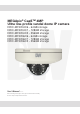
MEGApix® CaaSTM 4MP Ultra low-profile vandal dome IP camera DWC-MF4Wi4C6 - 64GB storage DWC-MF4Wi4C1 - 128GB storage DWC-MF4Wi4C2 - 256GB storage DWC-MF4Wi6C6 - 64GB storage DWC-MF4Wi6C1 - 128GB storage DWC-MF4Wi6C2 - 256GB storage User’s Manual Ver. 03/20 Before installing and using the camera, please read this manual carefully. Be sure to keep it handy for future reference.
Safety Information CAUTION RISK OF ELECTRIC SHOCK. DO NOT OPEN. CAUTION: TO REDUCE THE RISK OF ELECTRIC SHOCK, DO NOT REMOVE COVER (OR BACK) NO USER SERVICEABLE PARTS INSIDE. REFER SERVICING TO QUALIFIED SERVICE PERSONNEL. Warning Precaution This symbol indicates that dangerous voltage consisting a risk of electric shock is present within this unit.
Important Safety Instructions 1. Read these instructions. - All safety and operating instructions should be read before installation or operation. 2. Keep these instructions. - The safety, operating and use instructions should be retained for future reference. 3. Heed all warnings. - All warnings on the product and in the operating instructions should be adhered to. 4. Follow all instructions. - All operating and use instructions should be followed. 5. Do not use this device near water.
Table of Contents Introduction Product & Accessories......................................................................................................................................................................5 Parts Name...........................................................................................................................................................................................6 Installation Disassembling the Camera........................................................
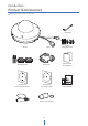
Introduc�on - Product & Accessories Note : Micro SD Card is built-in in this camera.
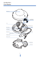
Introduction - Part Name Dome Cover Test Monitor Cable Connector Lens Tilt Stopper Screw Gimbal SD Card Slot Reset Button Bottom Case Bezel RJ-45 Connector Waterproof cap DC Power Jack Mount Plate Plate Hook 6
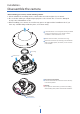
Installa�on - Disassemble the camera Before installing your camera, read the following cau�ons. 1. Check whether the mounting surface can bear five �mes the weight of your camera. 2. Do not let the cables get caught in improper place or the electric line cover to be damaged. It may cause a breakdown or fire. 3. When installing your camera, do not allow any person to approach the installa�on site. If you have any valuable things under the place, move them away.
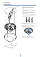
Installa�on - Installa�on Template Sheet 1 Disassemble the camera. See the sec�on ‘Installa�on - Disassemble the camera’ for details. 22 2 Using the template sheet, mark and drill the necessary holes. 3 Connect the network cable and power cable respec�vely. See the sec�on 'Installa�on Cabling' for details. Put the Lan cable into (a), then (b) will be assembled to (a) �ghtly. As a final step, (c) need to be assembled to (b) without making any space.
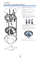
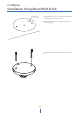
Installa�on - Installa�on Using Mount Plate Template Sheet 2 1 Disassemble the camera. See the sec�on ‘Installa�on Disassemble the camera’ for details. 2 Using the template sheet, make the cabling hole on the wall/ceiling. 3 A�er passing the cables through the hole, fix the mount plate on the template sheet. 4 Connect the network cable and power cable respectively. See the sec�on 'Installa�on - Cabling' for details. Put the Lan cable into (a), then (b) will be assembled to (a) �ghtly.
Installation - Installation Using Mount Bolt & Nut Template Sheet 10 1 Disassemble the camera. See the section ‘Installation Disassemble the camera’ for details. 2 Using the template sheet, make the cabling holes on the ceiling panel. 3 Insert the 2 mount bolts into bottom case of camera.
Installa�on - Installa�on Using Mount Bilt & Nut 11 4 Insert the mount bolts into template holes a�er connec�ng the cable. 5 Fix the bo�om case by �ghtening mount nuts to mount bolts on the ceiling panel. 6 To achieve desired view direc�on and orienta�on, rotate 3-axis gimbal. To fix the se�ng, �ghten the �lt stopper screw. 7 A�ach the dome cover to the bo�om case. 8 Detach the protec�on film from the dome cover.
Installation - Cabling Two Options Use a PoE-enabled switch to connect data and power through a single cable and begin viewing and recording images instantly. A non-PoE switch will require an adaptor for power transmission. 1. Using a PoE-Enabled Switch The Camera is PoE-compliant, allowing transmission of power and data via a single Ethernet cable. 2. Using a Non-PoE Switch If a PoE-enabled switch is not used, use a power adaptor for power transmission and non-PoE switch for data transmission.
Installa�on - SD Memory Card The memory card is an external data storage device that has been developed to offer an en�rely new way to record and share video, audio, and text data using digital devices. Micro Warning : Do not remove the built-in micro SD card which has been qualified CAAS TM purpose. Make sure check the built-in micro SD card at the system before installa�on. (Other Micro SD cards may not work properly.
Network setup - DW IP FinderTM Thumbnail view Firmware version Select network to scan Filter device type to scan Scan devices Show/hide thumbnail view Refresh thumbnail view Camera's uptime Open device configuration settings Bulk IP assignment Device's information Firmware upgrade 1 Go to : http://www.digital-watchdog.com and search for ‘IP Finder’ on the quick search bar at the top of the page. 2 The latest IP Finder software will appear in the search results.
Network Setup - Quick Start of Network Connection Please follow the steps below to complete the initial setup of the network function. 11. Access your IP Camera via the Internet : If you use a static IP address assigned by your ISP 1) Open Internet Explorer. 2) Type the IP of the IP Camera. 3) If you use a router, type the routers’ static IP and the web port number of the IP Camera. Please do not power on the IP Camera until instructed.
Network Setup - DDNS Registration If you have DYNAMIC IP service from your Internet Service Provider (ISP), you can’t tell the current IP address of the IP Camera. To solve this problem, you have to register to our DDNS service. At first, you have to check if you are using dynamic addressing. If so, register your IP Video Server on our DDNS website before you configure, setup, or install the IP Camera. Even though your IP is not dynamic, you will get benefit if you register to DDNS.
Network Setup - Guide to Network Environment Please configure the IP Camera at the installation site. You must determine your network scenario in order to configure the IP Camera with the proper TCP/IP settings. This tutorial will guide you through the process. Before actually configuring the IP Camera, determine settings to be applied. Record those settings to be used to configure your IP Camera for reference. 5. The following descriptions are several basic network scenarios.
Network Setup - Setup Case A, B Configure your IP Camera’s TCP/IP properties as follows : Case A: Dynamic IP + Personal Router [Most SOHO] 1. Network Type : STATIC (even though you have Dynamic IP from your ISP, use STATIC on the IP Camera) Camera 2. Internet Address : A private IP address such as 192.168.0.200 (Example) PC You need to assign an IP address to the IP Camera just as you do with PC.
Network Setup - Setup Case C, D Case D: Dynamic IP + DSL/Cable Modem [Connected directly to the IP Camera] Case C: Static(Fixed) IP [Dedicated line directly to the IP Camera] Camera Camera Phone Line or CATV Cable/xDSL Modem (ISP Provided) Public Line Gateway or Router at ISP Internet Internet Configure your IP Camera’s TCP/IP properties as follows : To connect the IP Camera directly to a modem, power down and reset the modem.
Network Setup - Port Forwarding After entering the correct TCP/IP settings, you are ready for ‘Port Forwarding’(Cases A, B). 1. Please record the TCP/IP settings of your IP Camera for future reference. You may need this information to access your IP Camera and to configure ‘Port Forwarding’. IP Camera TCP/IP Settings IP Address Subnet Mask Default Gateway Preferred DNS Server DDNS Server Web Port 2. After clicking ‘Apply’, the system will prompt for reboot.
Network Setup - Starting IP Camera After forwarding correctly the Web Port, through your router (if applicable), install the IP Camera in a proper location. 1. Locate the serial number located on the label attached to the bottom of the IP Camera, you will need this for DDNS registration. 2. Connect the IP Camera to your router or cable/DSL modem (per your network scenario) via a Cat5/5e UTP Ethernet network cable. 3. Supply power to the IP Camera. 4.
Web Viewer Screen - Basic Screen Web viewer is optimized with explorer10 or above version and Firefox. If VLC is not installed or VLC plugin is not supported (Chrome), Live buffering and Channel select menu on 3, 4 will be changed to Live Viewer menu, and then if HTML5(MJPEG) is selected on Live Viewer menu, then you can check the video. Live video display. This is the region for live video stream from the camera. Setup popup button.
Setup - Video & Audio Setup Video Configuration Detail Page - When you selects an item from the menu, you can set the details for the selected item.
Setup - Video & Audio Setup Video Configuration Live Video Channel Setup - The video can be configured to variety settings with a combination of codec and resolution. The camera performance has to be considered when setting multiple channels. This effects on the performance of the camera. Codec - Choose the video codec. According to the selected codec, the subcategories can be changed automatically. Description - Input the additional description about the selected channel. Max.
Setup - Video & Audio Setup Video Configuration GOP(Group of Pictures) Size - Set up the number of frames (P-frame) which contain only changed information based on basic frame (I-frame). Regarding videos with lots of movement, if you set GOP size bigger, only the number of P-frames is bigger. As a result, video resolution will be low but ‘File size’ and ‘Bit-rate can be decreased. GOP(Group of Pictures) Size is.. I-frame and P-frame can be created for MPEG4 and H.264 video compression.
Setup - Video & Audio Setup Video Configuration Bitrate Mode - Select the bitrate control scheme of video compression from CBR (Constant Bit Rate) or VBR (Variable Bit Rate). CBR - To guarantee the designated constant bit rate, the quality of video are controlled in this mode. Therefore, the quality of video is likely to be varying when network traffic is changing. VBR - To guarantee the designated quality, the bit rate of video stream is changed in this mode.
Setup - Video & Audio Setup OSD Configuration Date / Time - Display the current time. User Text - Output the TEXT entered by the user. Support a maximum of 30 characters. Click ‘Apply’ to make above setting effective.
Setup - Video & Audio Setup Region of Interest Configuration Region of interest function gives much more efficiency picture quality for indicated area to improve picture qualities of movement scene at the same bandwidth. Stream - Select the Stream. Currently it supports only Channel1. Activation - The Region of interest can be enable or disable. Quality - Set the quality of the set area. Click ‘Save’ to save the current settings. Click 'Cancel' to return to the previous setting.
Setup - Video & Audio Setup Privacy Mask Configuration Use this function to mask areas that you want to hide on screen to protect privacy. Activation - The Privacy mask function can be enable or disable. Area - Select the Area1 ~ Area16 and Set the privacy area. Click ‘Save’ to save the current settings. Click 'Cancel' to return to the previous setting. Click ‘Clear Area' to delete the selected Area1~Area16.
Setup - Camera Setup Camera Image Adjustment Sharpness - Using this control, sharpness of image can be adjusted to meet your preference. Brightness - Using this control, brightness of image can be adjusted to meet your preference. Contrast - Using this control, contrast of image can be adjusted to meet your preference. Saturation - Using this control, Saturation of image can be adjusted to meet your preference. Hue - Using this control, Hue of image can be adjusted to meet your preference.
Setup - Camera Setup Camera Exposure Settings Auto Exposure - Automatic exposure(AE) automatically sets the aperture or shutter speed, based on the external lighting conditions for the photo. Exposure Level - If this value is increases, the image becomes brighter. AE metering - AE metering mode refers to the way in which a camera determines the exposure. Shutter Speed - If this speed is faster, the moving object can be photographed without the ghost effect.
Setup - Camera Setup Camera Day & Night Settings Day & Night - Auto: In this mode, the IR cut filter is removed automatically depending on the light condition around. - Day: In this mode, the IR cut filter is applied to the image sensor all the time. Thus, the sensitivity will be reduced in the dark light condition but the better color reproduction performance are obtained. - Night: In this mode, the IR cut filter on the image sensor is removed all the time.
Setup - Camera Setup Camera Backlight Settings This is a feature used for problematic light conditions where the contrast from light to dark areas is very high. WDR (Wide Dynamic Range) - The WDR function can be enable or disable. WDR Level - Select the WDR level depending on the difference in brightness between the darkest and lightest part of an image. Click ‘Save’ to save the current settings. Click 'Cancel' to return to the previous setting. Click 'Default' to settings to the factory defaults.
Setup - Camera Setup Camera White Balance Activation - White Balance can be enable or disable. White Balance Mode - Select White Balance depending on the lighting conditions. RGB Gain - The R/G/B gain can be set only when the White Balance Mode is set to Manual. Click ‘Save’ to save the current settings. Click 'Cancel' to return to the previous setting. Click 'Default' to settings to the factory defaults.
Setup - Camera Setup Camera Image Enhancement 3D Noise Reduction - 3DNR function enables to suppress noise and retain good video quality in low light conditions. Mirror - Reverse the video from side to side. Flip - Reverse the video from up to down. Click ‘Save’ to save the current settings. Click 'Cancel' to return to the previous setting. Click 'Default' to settings to the factory defaults.
Setup - Camera Setup Video Enhancement Flicker - This function Enable to enhance the flicker situation. Click ‘Save’ to save the current settings. Click 'Cancel' to return to the previous setting. Click 'Default' to settings to the factory defaults.
Setup - Network Setup Network Status This menu will show you all the information of Network setting in the camera. However, you cannot change those here.
Setup - Network Setup Network Settings Network Type - Define network IP address type from the Static Mode for the fixed IP or the Dynamic Mode by the dynamic IP address. If you select the Static Mode, you must fill out IP Address, Subnet Mask, Gateway, DNS Server and all ports. If you select the Dynamic Mode, the IP address will be allocated automatically by DHCP equipment. If you click the Apply button to update changes, the system will be re-booted.
Setup - Network Setup Auto IP Settings General Setting - Auto IP Settings function can be enable or disable. Auto IP Settings Information - It displays the unique id or Auto IP address. Click ‘Apply’ to make above setting effective.
Setup - Network Setup ONVIF Settings Authentication None: Allows to access without ONVIF authentication. WS - Usertoken: Allows to access with WS-User Token of ONVIF authentication. WS - Usertoken + Digest: Allows to access with WS-User Token and Digest of ONVIF authentication. Discovery Mode - The discovery function can be enable or disable. Click ‘Apply’ to make above setting effective.
Setup - Network Setup UPNP Settings General Setting - UPNP function can be enable or disable. Friendly Name - Define the friendly name. Click ‘Apply’ to make above setting effective.
Setup - Network Setup DDNS Settings DDNS Disable - If it is selected, DDNS service does not work. Public DDNS - To use public DDNS service, select a site address listed in the list. After filling out the Host Name of the site, the setup is completed by entering User Name and Password registered in that DDNS site. DDNS Provider Site Address DynDNS www.dyndns.com No-IP www.no-ip.
Setup - Network Setup FTP Settings To transfer / save the image to the relevant sites through FTP, then FTP needs to be setup. General Setting - FTP function can be enable or disable. FTP Server Address - Define FTP Server IP Address. If IP Address form is incorrect, a Message box will be shown to try again. FTP Upload Path - Define a path in FTP server to store video. For the path name, English Alphabets, numbers and special characters ( / ~ !@ $ ^ ( ) _ - { } [ ] ; , ) can be used.
Setup - Network Setup SMTP Settings To send / save the image to the relevant sites by Email, SMTP needs to be setup. General Setting - SMTP function can be enable or disable. Mode - Select Security mode of SMTP from Plain or SSL / TLS. After checking account setup of your SMTP Server, you may select one. SMTP Server Address - Define the SMTP Server Address. If the IP Address form is incorrect, a Message box will be shown to try again.
Setup - Network Setup SNMP Settings SNMPv1/SNMPv2 - Select the SNMPv1/SNMPv2 option and type the names of Read community and Write community. SNMP trap can be used to check periodically for operational thresholds or failures that are defined in the MIB. SNMP Trap - SNMP trap can be enable or disable. SNMPv3 contains cryptographic security, a higher security level, which allows you to set the Authentication password and the Encryption password. Mode - Select the either Read or Read/Write mode.
Setup - Network Setup RTSP Information Target Stream - Select the channel you want to set. Time out - Set the RTSP time out. The session is disconnected after the specified time out. RTP Multicast - Check RTP Multicast On/Off. To activate RTP Multicast. 1. Click “On” button 2. Enter accessible RTP Multicast IP, port for video stream control, RTP packet TTL 3. Click “Apply” button. It is possible to set each RTP Multicast for CH1~3. Click ‘Apply’ to make above setting effective.
Setup - Trigger Action Setup Action Rules Configuration Action rules List - It indicates the custom action rule information added to Action rules list. Click ‘Add’ to add custom action rules. Click ‘Modify' to modify selected item from the action rules list. Click 'Delete' to delete selected item from the action rules list.
Setup - Trigger Action Setup Action Rules Add / Modify Name - Define name of action rules. Action1 ~ Action5 - Select the action to take If the event occurs. Click ‘Save’ to save the current settings. Click 'Cancel' to return to the previous menu.
Setup - Trigger Action Setup Image Transfer Configuration Pre / Post Alarm Image - Image Transfer due to event is configured by setting Image transfer rate and Pre / Post alarm duration. Descriptions Number of Image Define Number of image transferred per second. Pre-alarm Duration Define duration of image transfer before an event. Post-alarm Duration Define duration of image transfer after an event. Click ‘Apply’ to make above setting effective.
Setup - Event Setup Event Rules Configuration Event Rules List - It indicates the custom Event Rule information added to Event Rules list. Click ‘Add’ to add custom event rules. Click ‘Modify' to modify selected item from the event rules list. Click 'Delete' to delete selected item from the event rules list.
Setup - Event Setup Event Rules Configuration Name - Define the Event rule name. Event - Select the event among motion detection, network disconnection, temperature critical. Click 'Cancel' to return to the previous setting. You need a event one more. Rules - Select the action rule defined in the Trigger Action-Action rule menu. Click ‘Save’ to save the current settings. Click 'Cancel' to return to the previous setting.
Setup - Event Setup Motion Detection Configuration Motion Detection - It shows the Motion event status. Event Alert Icon( ) appears if ‘Motion Detection’ is activated. Area - Set the motion detected area. You can set up to four areas. Activation - Enable or Disable motion detection function. Sensitivity - Define the sensitivity of motion detection. If High value is selected, it will detect very small motion while it becomes relatively insensitive when Low value is selected.
Setup - Event Setup Temperature Mode - Select the either Fahrenheit and Celsius. Threshold - Define the temperature at which the event trigger is occurred. Temperature - It indicates the current temperature of the IP camera. Click ‘Apply’ to make above setting effective.
Setup - Edge Setup DW Spectrum® Edge Version - Displays the version of DW Spectrum® edge (media server) installed in the camera. Status - Displays the status of the DW Spectrum® edge (media server) installed in the camera. Wait until the status of the server is marked as 'alive'. Select a new version of DW Spectrum® edge (media server) file to update and upload. Update with selected file. If you select file, it will be activated.
Setup - Edge Setup Storage Configuration Display the SD card information mounted from device. When you select the item in Storage list, You can set the functions related to the SD card.
Setup - Edge Setup Storage Configuration Storage Size - Total capacity of SD card and the remainder of it are displayed. Unmount - Remove the SD card from the device. UNMOUNT cannot be done when EDGE (Media server) is running. Format - Delete the all contents that stored in SD card. FORMAT cannot be done when EDGE (Media server) is running..
Setup - Security Setup IP Address Filter Configuration IP Address Filter - IP filter function can be enable or disable. IP Filter Type - Select the recording IP filter type. Click ‘Apply’ to make above setting effective. Filter IP Address - Display the filtered IP address. IP Address - Define the IP address you want to apply the IP filter. Click ‘Add’ to add the ip address to the list. Click ‘Remove’ to remove the ip address selected in the list. Click ‘Remove All’ to remove all ip in the list.
Setup - Security Setup RTSP Authentication Configuration RTSP Authentication - RTSP Authentication can be enable or disable. Click ‘Apply’ to make above setting effective.
Setup - Security Setup IEEE 802.1X Configuration The feature is needed when connecting the camera to the network protected by the IEEE 802.1X. IEEE 802.1x - The IEEE 802.1x feature can be enable or disable. Protocol - MD5 : It provides one-way password-based network authentication of the client. - PEAP : It is similar to TTLS in that it does not require a certificate on the client side. - TTLS / MD5 : It does not require a certificate on the client side.
Setup - Security Setup HTTPS Configuration HTTPS encrypts session data over SSL or TLS protocols instead of using plain text in socket communications. Certificate - Select an installed certificate. If you can not select a certificate, please install the certificate from the Security->Certificates menu. HTTPS connection Policy - Select one of “HTTP”, “HTTPS”, “HTTP and HTTPS” depending on the connected user authority. Click ‘Apply’ to make above setting effective.
Setup - Security Setup Certificates Configuration Server/Client Certificates - It show the installed certificates. Create Self-Signed Certificate - A self-signed SSL certificate is an identity certificate signed by its own creator. but they are considered to be less trustworthy. Properties - Shows information about the selected certificate. Delete - Delete the selected certificate.
Setup - Security Setup Certificates Configuration Detail for Install Certification. Certificate From Signing Request - Select to install signed certificate returned from the CA. Certificate And Private Key - Select to install Certificate And Private Key to install a certificate and private key. - Use Separate Key : Too install certificate uploading Certificate and Private Key file. - PKCS#12” : “PKCS#12” is cryptography standard. if you want to install using PKCS#12, must enter the password.
Setup - Security Setup Service Configuration Telnet - The Telnet function can be enable or disable. Click ‘Apply’ to make above setting effective.
Setup - System Setup System Information System Capability information. Device Name - You can define the device name. Click ‘Apply’ to make above setting effective.
Setup - System Setup Firmware Update Version Information - It shows the current Firmware Version in the system. Web Update - Select the Firmware file in your computer by clicking [Select file] button. Start F / W Update - Click this button to start update. Progress of uploading will be displayed using Progress Bar. If you assign the wrong file name, an error massage will be shown. Warning: 1. Do not turn off the power of camera during the Firmware update. Otherwise, the system can be stuck to be unstable.
Setup - System Setup Firmware Update FTP Server Address - Define FTP Server IP Address. If IP Address form is incorrect, a Message box will be shown to try again. FTP Port - Define the FTP Server Port. If Port is not appropriate, it is impossible to access to FTP Server. User ID - Define User ID to access to the FTP Server. Fill out the correct User ID registered in the FTP Server. Password - Define Password to access to the FTP Server. Fill out the correct Password registered in the FTP Server.
Setup - System Setup Date & Time Settings TimeZone Setup - Choose TimeZone for camera. It will be activated after clicking ‘Apply’ button. Prior to setting below ‘New Camera Date & Time’, set correct Timezone first. Time Format - Select the time format yy-mm-dd or mm/dd/yy. Current Date & Time - Shows the current date and time setting in the Camera. Synchronize with my computer - Set the date / time using those of PC currently connected. Setup manually - Set the date / time by typing manually.
Setup - System Setup Users Management Users - List all the user accounts for authentication. Add - Register a new user ID Enter a new user ID except Admin since it exists. Password Enter the user Password. Enter the user Password again for verification. Verify User Authority Select Operator or Viewer. Viewer : Only monitoring is allowed. Operator : Most of the functions are allowed except ‘Setup’. Administrator : All functions are allowed. The ID and Password are limited to 10 characters.
Setup - System Setup System Log Filter - Select a date, sort or type of log to filter the log. Click the 'Refresh' button to refresh the log list. Click 'Filter' to view the filtered log. System Log List - The filtered log is displayed.
Setup - System Setup Factory Reset Reset to the factory defaults - Return the setup to the factory default. All - Reset all Settings to the factory defaults. Except Network Settings - Except Network related settings, reset all others to the factory default. Click ‘Apply’ to make above setting effective.
Setup - System Setup Restart If you click the ‘RESTART’ menu, a message box will be shown to confirm. Click the ‘OK’ button to restart.
Appendix A : Current TCP/IP Settings If your IP settings are obtained automatically, you could use the MS-DOS prompt (or Command Prompt) to determine your IP address. For information on how to do this, please read the FAQ. 1. Windows 7 Users 2.
Appendix - B : Changing IP address and subnet mask 1. Windows 7 Users 2. Windows 10 Users Start Start Control Panel Settings Network and sharing center Network & Internet Click on Change adapter options in Ethernet Manage network connections Select the Ethernet, Right click and choose Properties Properties Select Internet Protocol Ver.4 (TCP/IPv4) Select Internet Protocol Ver.
Appendix - FAQ 1. My POWER light is not on? Power is not being supplied to the unit. Please use the power supply shipped with the unit and verify that a power source is active from the attached power outlet used to connect the adapter. You can test this by plugging in any other electrical device and verify its operation. After using the power supply shipped with the product, checking the power source, and reinserting the power connector into the IP Camera, please call our Support Center.
Specifications - Dimension Unit: inches (mm) 1.35" (34.3mm) 1.58" (40.2mm) 4.
Warranty Information Digital Watchdog (referred to as “the Warrantor”) warrants the Camera against defects in materials or workmanships as follows: Labor: For the initial five (5) years from the date of original purchase if the camera is determined to be defective, the Warrantor will repair or replace the unit with new or refurbished product at its option, at no charge. Parts: In addition, the Warrantor will supply replacement parts for the initial two (2) years.
Limits & Exclusions There are no express warranties except as listed above. The Warrantor will not be liable for incidental or consequential damages (including, without limitation, damage to recording media) resulting from the use of these products, or arising out of any breach of the warranty. All express and implied warranties, including the warranties of merchantability and fitness for particular purpose, are limited to the applicable warranty period set forth above.
DW® east coast office and warehouse 8 $SFOTIBX 4U 5BNQB '- DW® west coast office and warehouse #MPPNGJFME "WF $FSSJUPT $BMJGPSOJB 64" 1) ] '"9 XXX %JHJUBM 8BUDIEPH DPN UFDIOJDBMTVQQPSU!EXDD UW 5FDIOJDBM 4VQQPSU 1) 64" $BOBEB +1 (904) 999-1309 *OUFSOBUJPOBM 'SFODI $BOBEJBO 5FDIOJDBM 4VQQPSU hPVST .