.&("QJY¥ .1 5VSSFU *1 $BNFSB %8$ .
4BGFUZ *OGPSNBUJPO $"65*0/ 3*4, 0' &-&$53*$ 4)0$, %0 /05 01&/ $"65*0/ 50 3&%6$& 5)& 3*4, 0' &-&$53*$ 4)0$, %0 /05 3&.
*NQPSUBOU 4BGFUZ *OTUSVDUJPOT 3FBE UIFTF JOTUSVDUJPOT "MM TBGFUZ BOE PQFSBUJOH JOTUSVDUJPOT TIPVME CF SFBE CFGPSF JOTUBMMBUJPO PS PQFSBUJPO ,FFQ UIFTF JOTUSVDUJPOT 5IF TBGFUZ PQFSBUJOH BOE VTF JOTUSVDUJPOT TIPVME CF SFUBJOFE GPS GVUVSF SFGFSFODF )FFE BMM XBSOJOHT "MM XBSOJOHT PO UIF QSPEVDU BOE JO UIF PQFSBUJOH JOTUSVDUJPOT TIPVME CF BEIFSFE UP 'PMMPX BMM JOTUSVDUJPOT "MM PQFSBUJOH BOE VTF JOTUSVDUJPOT TIPVME CF GPMMPXFE %P OPU VTF UIJT EFWJDF OFBS XBUFS 'PS FYBNQMF OFBS
Table of Contents 1 2 3 4 5 6 Product & Accessories .....................................................................................5 Parts and Description .......................................................................................6 Installation .........................................................................................................7 Cabling...............................................................................................................8 Remote Preview ......
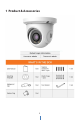
1 Product & Accessories 5
2 Parts and Description 6
3 Installation 1. 2. 3. 4. 5. 6. 7. Before installing the camera, make sure the mounting surface can bear three times the weight of your camera. Do not let the cables get caught in improper places or the electric line cover to be damaged. This may cause a breakdown or fire. Using the mounting template sheet or the camera itself, mark and drill the necessary holes in the wall or ceiling. Pass the wires through and make all necessary connections. See cabling section for more information.
4 Cabling 1. 2. NETWORK CONNECTIONS – If you are using a PoE Switch, connect the camera using an Ethernet cable for both data and power. NETWORK CONNECTIONS – If you are using a non-PoE switch, connect the camera to the switch using an Ethernet cable for data transmission and use a power adapter to power the camera.
5 Remote Preview To log in to the camera, open an Internet Explorer page and input the camera’s IP address. If you are connecting to the camera for the first time, be sure to download the ActiveX control. After downloading, a login window will pop up as shown below. Input the username and password to log in. ) The default username is “admin”; the default password is “admin”. After you log in, you will see the following window.
Icon z z Description Icon Description Original size Scene change indicator icon Appropriate size Abnormal clarity indicator icon Auto Color abnormal indicator icon Full screen Motion alarm indicator icon Start/stop live view Start/stop recording Enable/disable audio Zoom in Snap Zoom out When motion detection alarm is triggered, the people icon will turn red. In full screen mode, double click to exit. 6 Remote Live Surveillance 6.
6.1.2 Date and Time Go to ConfigÆSystemÆDate and Time. Please refer to the following interface. You can select the time zone and DST as required. Click “Date and Time” tab to set the time mode. 6.1.3 Local Config Go to ConfigÆSystemÆLocal Config. You can set the storage path of the captured pictures and video records. You can also enable or disable the video audio. 6.2 Image Configuration Image Configuration includes Display, Video/Audio, OSD, Video Mask and ROI Config. 6.2.
x x x x x x x x x x Brightness: Set the brightness level of the camera’s image. Contrast: Set the color difference between the brightest and darkest parts. Hue: Set the total color degree of the image. Saturation: Set the degree of color purity. The purer the color is, the brighter the image is. Sharpness: Set the resolution level of the image plane and the sharpness level of the image edge. Noise Reduction: Decrease the noise and make the image more thorough.
x x x x x x x x x x 60Hz: Make sure the horizontal stripes will not appear in the image while the device is adjusting the exposure automatically according to the brightness of the scene when the electric supply is 60Hz. White Balance: Adjust the color temperature according to the environment automatically. Frequency: 50Hz and 60Hz can be optional. Day/night Mode: Please choose the mode as needed. Sensitivity: High, middle and low can be selected.
x x x x x x x x x x the recording. VBR means that the compression bitrate can be adjustable according to the change of the video resources. This will help to optimize the network bandwidth. Bitrate: Please choose it according to the actual network situation. Video Quality: When VBR is selected, you need to choose image quality. The higher the image quality you choose, the more bitrate will be required. I Frame interval: It is recommended to use the default value.
6.2.4 Video Mask Go to ImageÆVideo Mask interface as shown below. You can set 4 mask areas at most. To set up video mask: 1. Enable video mask. 2. Click “Draw Area” button and then drag the mouse to draw the video mask area. 3. Click “Save” button to save the settings. 4. Return to the live to see the following picture. Clear the video mask: Go to video mask interface and then click “Clear” button to delete the current video mask area. 6.2.
1. Check “Enable” and then click “Draw Area” button. 2. Drag the mouse to set the ROI area. 3. Set the level. 4. Click “Save” button to save the settings. Now, you will see the selected ROI area is clearer than other areas especially in low bitrate condition. 6.3 Alarm Configuration Alarm configuration includes two submenus: Motion Detection and Alarm Server. 6.3.1 Motion Detection Go to AlarmÆMotion Detection to set motion detection alarm.
1. 2. Check “Enable Alarm” check box to activate motion based alarm, choose alarm holding time and set alarm trigger options. x Trigger Email: If “Trigger Email” and “Attach Picture” checkbox is checked (email address shall be set first in the Email configuration interface), the captured pictures and triggered event will be sent into those addresses. x Trigger FTP: If “Trigger FTP” and “Attach Picture” checkbox is checked, the captured pictures will be sent into FTP server address.
Week schedule Set the alarm time from Monday to Sunday for alarm every day in one week. The lengthwise means one day of a week; the rank means 24 hours of a day. Green means selected area. Blank means unselected area. “Add”: Add the schedule for a special day. “Erase”: Delete holiday schedule. Day schedule Set alarm time for alarm in some time of a special day, such as holiday.
6.4 Event Configuration Event configuration includes four submenus: Object Removal, Exception, Line Crossing and Intrusion. Note: Some software versions of this series of cameras may not support the following functions. Please take actual displayed interface as final. 6.4.1 Object Removal To set object removal: Go to ConfigÆEventÆObject Removal interface as shown below. 1. 2. 3. 4. Enable object removal detection and then select the detection type.
Set the alarm area number and then input the alarm area name on the right side. You can add 4 alarm areas at most. Click “Draw Area” button and then click around the area where you want to set as the alarm area in the image on the left side (the alarm area should be a closed area). Click “Stop Draw” button to stop drawing. Click “Clear” button to delete the alarm area. Click “Save” button to save the settings. 5. Set the schedule of the object removal detection.
There are so many trees near the road and cars running on the road, which make the scene too complex to detect the removal objects. 6.4.2 Exception To set exception detection: Go to ConfigÆEventÆException interface as shown below. 1. 2. 3. 4. Enable the relevant detection as required. x Scene Change Detection: The relevant alarms will be triggered if the scene of the monitor video has changed. x Video Blur Detection: The relevant alarms will be triggered if the monitor video is blurry.
Drag the slider to set the sensitivity value or directly input the sensitivity value in the textbox. Click “Save” button to save the settings. The sensitivity value of Scene Change Detection: The higher the value is, the more sensitive the system responds to the amplitude of the scene change. The sensitivity value of Video Blur Detection: The higher the value is, the more sensitive the system responds to the defocus of the device image. You should just the value according to the real situation.
2. 3. 4. Set alarm trigger options. The setting steps are the same with that of motion detection. Please refer to motion detection chapter for details. Click “Save” button to save the settings. Set area and sensitivity of the line crossing alarm. Click “Area and Sensitivity” tab to go to the interface as shown below. Set the cordon number and direction. You can add 4 cordons at most. Direction˖A<->B, A->B and A<-B optional. It is the crossing direction of the intruder who crosses over the alarm line.
Here we take some improper application scenarios for instance. There are so many trees near the road and cars running on the road, which make the scene too complex to detect the crossing objects. The ground is covered with vegetation; at the right of the fence is a gym where people pass by frequently. The above mentioned environment is too complex to detect the crossing objects. 6.4.
1. 2. 3. 4. 7. 8. 9. Enable region intrusion detection alarm and set the alarm holding time. Set alarm trigger options. The setting steps are the same with that of motion detection. Please refer to motion detection chapter for details. Click “Save” button to save the settings. Set the alarm area of the intrusion detection. Click “Area” tab to go to the interface as shown below. Set the alarm area number on the right side. You can add 4 alarm areas at most.
video image will change so greatly that the algorithm will stop working temporarily. Try not to enable intrusion detection when light changes greatly in the scene. Try to install the camera at a certain angle of depression. Adequate light and clear scenery are very important to intrusion detection. Adjust the camera to make the detection area in the center of the video image. The detected object should be in the detection area for about two seconds at least.
Use IP address (take IPv4 for example)-There are two options for IP setup: obtain an IP address automatically by DHCP protocol and use the following IP address. Please choose one of the options for your requirements. Use PPPoE-Click “PPPoE Config” tab to go to the interface as shown below. Enable PPPoE and then enter the user name and password from your ISP. You can choose either way of the network connection. If you use PPPoE to connect internet, you will get a dynamic WAN IP address.
6.5.2 Port Go to ConfigÆNetworkÆPort interface as shown below. HTTP port, Data port and RTSP port can be set. HTTP Port: The default HTTP port is 80. It can be changed to any port which is not occupied. Data Port: The default data port is 9008. Please change it as required. RTSP Port: The default port is 554. Please change it as required. 6.5.3 Server Configuration This function is mainly used for connecting network video management system. 1. 2. 3. Check “Enable”.
2. 3. Apply for a domain name. Take www.dvrdyndns.com for example. Input www.dvrdydns.com in the IE address bar to visit its website. Then click “Registration” button. Create domain name. After you successfully request your domain name, you will see your domain in the list.
4. 5. Input the username, password, domain you apply for in the DDNS configuration interface. Click “Save” button to save the settings. 6.5.5 SNMP To get camera status, parameters and alarm information and remotely manage the camera, you can set the SNMP function. Before using the SNMP, please download the SNMP software and set the parameters of the SNMP, such as SNMP port, trap address. 1. Go to ConfigÆNetworkÆSNMP.
2. 3. Check the corresponding version checkbox (Enable SNMPv1, Enable SNMPv2, Enable SNMPv3) according to the version of the SNMP software you download. Set the “Read SNMP Community”, “Write SNMP Community”, “Trap Address”, “Trap Port” and so on. Please make sure the settings are the same as that of your SNMP software. Note: Please use the different version in accordance with the security level you required. The higher the version is, the higher the level of the security is. 6.5.
6.5.8 Email If you need to trigger Email when an alarm happens or IP address is changed, please set the Email here first. Go to ConfigÆNetwork ÆEmail. Sender Address: Sender’s e-mail address. User name and password: Sender’s user name and password. Server Address: The SMTP IP address or host name. Select the secure connection type at the “Secure Connection” pull-down list according to actual needs. SMTP Port: The SMTP port. Send Interval(S): Set it as needed.
To Add FTP: Server Name: The name of the FTP. Server Address: The IP address or domain name of the FTP. Upload Path: The path of uploading the files. Port: The port of the FTP. Use Name and Password: The username and password are used to login the FTP. 6.6 Security Configuration 6.6.1 User Configuration Go to ConfigÆSecurityÆUser interface as shown below. Add user: 1. Click “Add” button to pop up the following textbox.
2. 3. 4. 5. 6. 7. Input user name in “User Name” textbox. Input letters or numbers in “Password” and “Confirm Password” textbox. Choose the use type. Input the MAC address of the PC in “Bind MAC” textbox. After binding physical address to the IP-CAM, you can access the device on this PC only. If the MAC address was “00:00:00:00:00:00” which means it can be connected to any computers. Click “OK” button and then the new added user will display in the user list. Modify user: 1.
Delete user: 1. Select the user you want to delete in the user configuration list box. 2. Click “Delete” button to delete the user. Note: The default super administrator cannot be deleted. 6.6.2 Online User Go to ConfigÆSecurityÆOnline User. You can view the user who is viewing the live video. 6.6.3 Block and Allow Lists Go to ConfigÆSecurityÆBlock and Allow Lists interface as shown below. Setting steps are as follows: Check “Enable IP address filtering” check box.
x Import & Export Settings You can import or export the setting information from PC or to device. Click “Browse” to select save path for import or export information on PC. Click “Import Setting” or “Export Setting” button. x Default Settings Click “Load Default” button to restore all system settings to default status. 6.7.2 Reboot Go to ConfigÆMaintenanceÆReboot. Click “Reboot” button to reboot the device.
6.7.4 Operation Log To query and export log: 1. Go to ConfigÆMaintenanceÆOperation Log. 2. 3. 4. Select the main type, sub type, start and end time. Click “Search” to view the operation log. Click “Export” to export the operation log.
7 Record Search Click Search to go to the interface as shown below. You can play the local video record. Before playing, please set the storage path of the video record in the local configuration interface and make sure there are record files. Choose the date and the start time and end time and then click “Search” button to search the record files. Double click the record file to play the record. The descriptions of the buttons on the playback interface are as follows.
8 Appendix Appendix 1 Q& A Q: How to find my password if I forget it? A˖Reset the device to the default factory settings. Default IP: 192.168.226.201; User name: admin; Password: 123456 Q͵Fail to connect devices through IE browser, why? A: Network is not well connected. Check the connection and make sure it is connected well. B: IP is not available. Reset the valid IP. C: Web port number has been revised: contact administrator to get the correct port number. D: Exclude the above reasons.
Q˖ ˖No sound can be heard, why? A˖Audio input device is not connected. Please connect and try again. B: Audio function is not enabled at the corresponding channel. Please enable this function.
9 Dimensions 41
8BSSBOUZ *OGPSNBUJPO %JHJUBM 8BUDIEPH SFGFSSFE UP BT iUIF 8BSSBOUPSw XBSSBOUT UIF $BNFSB BHBJOTU EFGFDUT JO NBUFSJBMT PS XPSLNBOTIJQT BT GPMMPXT -BCPS 'PS UIF JOJUJBM GJWF ZFBST GSPN UIF EBUF PG PSJHJOBM QVSDIBTF JG UIF DBNFSB JT EFUFSNJOFE UP CF EFGFDUJWF UIF 8BSSBOUPS XJMM SFQBJS PS SFQMBDF UIF VOJU XJUI OFX PS SFGVSCJTIFE QSPEVDU BU JUT PQUJPO BU OP DIBSHF 1BSUT *O BEEJUJPO UIF 8BSSBOUPS XJMM TVQQMZ SFQMBDFNFOU QBSUT GPS UIF JOJUJBM GJWF ZFBST 5P PCUBJO XBSSBOUZ PS PVU PG XBSS
-JNJUT BOE &YDMVTJPOT 5IFSF BSF OP FYQSFTT XBSSBOUJFT FYDFQU BT MJTUFE BCPWF 5IF 8BSSBOUPS XJMM OPU CF MJBCMF GPS JODJEFOUBM PS DPOTFRVFOUJBM EBNBHFT JODMVEJOH XJUIPVU MJNJUBUJPO EBNBHF UP SFDPSEJOH NFEJB SFTVMUJOH GSPN UIF VTF PG UIFTF QSPEVDUT PS BSJTJOH PVU PG BOZ CSFBDI PG UIF XBSSBOUZ "MM FYQSFTT BOE JNQMJFE XBSSBOUJFT JODMVEJOH UIF XBSSBOUJFT PG NFSDIBOUBCJMJUZ BOE GJUOFTT GPS QBSUJDVMBS QVSQPTF BSF MJNJUFE UP UIF BQQMJDBCMF XBSSBOUZ QFSJPE TFU GPSUI BCPWF 4PNF TUBUFT EP OPU BMMPX U
)FBERVBSUFST 0GGJDF 8 $SFOTIBX 4U 5BNQB '- 4BMFT 0GGJDF #MPPNGJFME "WF $FSSJUPT $BMJGPSOJB 64" 1) ] '"9 XXX %JHJUBM 8BUDIEPH DPN UFDIOJDBMTVQQPSU!EXDD UW 5FDIOJDBM 4VQQPSU 1) 64" $BOBEB *OUFSOBUJPOBM 'SFODI $BOBEJBO 5FDIOJDBM 4VQQPSU )PVST .